
Series is not automatically the best RV solar configuration, and parallel is not automatically the best choice for shade. Start by rejecting any topology that violates the exact controller’s voltage or current limits. Then compare the survivors using hot operating-voltage headroom, module matching, roof shade, controller inputs, cable-route constraints, and the complete protection plan.
The tested four-module example on this page produces three different results:
| Candidate | STC operating values | Corrected cold Voc | Fixture outcome |
|---|---|---|---|
| Four in series | 81.6 Vmp, 4.9 Aimp | 109.4 V | Blocked: above the documented 100 V example limit |
| Four in parallel | 20.4 Vmp, 19.6 Aimp | 27.4 V | Hard limits pass; hot Vmp unresolved |
| Two in series, two strings parallel | 40.8 Vmp, 9.8 Aimp | 54.7 V | Hard limits pass; hot Vmp unresolved |
These are synthetic module values tested against one documented controller example. They are not product recommendations, a wiring plan, or proof that either surviving topology is suitable for your RV.
Safety and limitations: PV modules can produce voltage whenever illuminated. Higher series voltage increases shock and arcing concern; more parallel strings increase available current and protection complexity. This page does not authorize roof access, opening equipment, separating connectors, measuring an energized array, or changing wiring. It does not select cable, connectors, fuses, breakers, disconnects, combiner equipment, grounding, bonding, routing, torque, or an isolation sequence. Use the exact current manuals and qualified RV solar service whenever safe isolation, roof work, connector compatibility, protection, or system design is uncertain.
Record the exact module, controller, battery, and temperatures
Do not choose a topology from panel wattage alone. The minimum planning record needs values from the exact module and controller revisions, plus site conditions that are not printed on either product.
| Record | Why it is needed | Block the decision when |
|---|---|---|
| Module Voc, Vmp, Isc, Imp, and Pmax at STC | Separates open-circuit, operating, short-circuit, operating-current, and power quantities | A marketplace listing, different model, or rounded marketing value replaces the datasheet |
| Voc temperature coefficient | Corrects maximum open-circuit voltage for cold conditions | It is missing, ambiguous, or given for a different electrical quantity |
| Vmp temperature behavior | Tests minimum operating-voltage headroom when cells are hot | The exact controller requires headroom but hot array Vmp cannot be established |
| Local minimum design temperature | Sets the cold condition for maximum Voc | A generic multiplier replaces a defensible local temperature input |
| Expected maximum cell temperature | Supports hot Vmp, not merely ambient-temperature, analysis | Roof heating and the module method are unresolved |
| Controller maximum PV Voc and Isc | Defines hard input boundaries for the exact model | Either limit is missing or a nearby controller model is substituted |
| Controller startup and operating range | Tests whether the array can start and remain in regulation across battery conditions | Only a maximum-voltage rating is known |
| Battery system voltage and charging ceiling | Establishes the voltage the controller must charge above | “12V battery” is used instead of the documented operating range |
| Controller PV-power and output-current rules | Separates permitted oversizing or clipping from input damage limits | A rule from another controller is copied over |
| Module match, orientation, shade map, and controller inputs | Determines whether strings can share one tracker sensibly | Mixed electrical curves or different roof conditions are assumed equivalent |
Victron’s installation guidance explicitly says to account for higher cold-weather Voc and to keep array Voc below the exact controller maximum. Morningstar’s MPPT input-power paper treats both ends of the temperature range: corrected maximum Voc must stay below the controller limit, while corrected minimum Vmp must remain high enough for consistent charging.
That is why a cold-Voc calculation is necessary but insufficient. It answers one maximum-voltage question. It does not answer whether a low-voltage parallel array retains enough headroom over a charging battery on a hot roof.
The physical installation record is a separate requirement. A valid arithmetic result says nothing about connector pairing, conductor ampacity, voltage drop, roof penetration, strain relief, overcurrent protection, disconnecting means, or safe commissioning. The RV electrical system overview explains where the solar controller fits within the larger DC power path; it does not make the PV side safe to handle.
Calculate series, parallel, and series-parallel arrays
For matched modules in this simplified fixture:
module count = modules per series string x parallel strings
array Vmp at STC = module Vmp x modules per series string
array Imp at STC = module Imp x parallel strings
array Voc at STC = module Voc x modules per series string
array Isc at STC = module Isc x parallel strings
array Pmax at STC = module Pmax x module count
The Go Power kit manual illustrates the basic distinction with product-specific arrays: voltage adds in series and current adds in parallel. The fixture uses the same arithmetic, but its module record is deliberately synthetic:
| Synthetic module field | Fixture value |
|---|---|
| Pmax | 100 W |
| Vmp | 20.4 V |
| Imp | 4.9 A |
| Voc | 24.3 V |
| Isc | 5.2 A |
| Voc coefficient | -0.28% per degree C |
| STC cell temperature | 25 degrees C |
Those rounded values do not identify or recommend a commercial panel. In a real calculation, take the complete set from one exact datasheet. Do not combine Voc from one revision with a temperature coefficient from another.
The controller side of the example is not synthetic. Victron’s BlueSolar 100/30 specifications list a 100 V maximum PV open-circuit voltage, 35 A maximum PV short-circuit current, 440 W nominal PV power on a 12 V system, and 30 A rated charge output. Those numbers belong to that controller example, not every device with “100/30” in its name.
Cold-Voc calculation
The fixture applies a linear coefficient example:
cold module Voc = 24.3 x [1 + (0.28 / 100) x (25 - -20)]
cold module Voc = 27.3618 V
At the synthetic local design minimum of -20 degrees C, the four-series string becomes:
27.3618 V x 4 = 109.4472 V cold array Voc
The same four modules looked like 97.2 Voc at STC, just under the controller’s 100 V label. Temperature correction changes that apparent pass into a block. A blanket 1.25 multiplier might also reject this particular case, but that does not validate the blanket method. Use the exact coefficient, temperature method, and local design condition required by the module and controller documentation. Morningstar’s string calculator exists for this exact kind of model-specific configuration screening and preserves its own assumptions and disclaimer.
Three tested candidates
| Fixture topology | Series x parallel | Vmp / Imp at STC | Voc / Isc at STC | Pmax | Cold Voc |
|---|---|---|---|---|---|
| Four-series | 4S x 1P | 81.6 V / 4.9 A | 97.2 V / 5.2 A | 400 W | 109.4472 V |
| Four-parallel | 1S x 4P | 20.4 V / 19.6 A | 24.3 V / 20.8 A | 400 W | 27.3618 V |
| Series-parallel | 2S x 2P | 40.8 V / 9.8 A | 48.6 V / 10.4 A | 400 W | 54.7236 V |
All three have the same nameplate Pmax because they use four equal 100 W modules. Topology changes array-side voltage and current, not the sum of module nameplate watts. Real output still depends on irradiance, cell temperature, orientation, shade, mismatch, soiling, wiring loss, controller conversion, battery acceptance, and system state.
Apply cold Voc, Isc, power, and voltage-headroom gates
Run the gates in order. A failed hard limit removes a candidate. A passed hard limit only allows the next question.
| Gate | Four-series | Four-parallel | 2S2P | Meaning |
|---|---|---|---|---|
| Cold array Voc below 100 V example maximum | Fail: 109.4 V | Pass: 27.4 V | Pass: 54.7 V | Four-series is blocked |
| Array Isc below 35 A example maximum | Pass: 5.2 A | Pass: 20.8 A | Pass: 10.4 A | No candidate fails this recorded input limit |
| Nameplate PV power versus 440 W example rating | 400 W | 400 W | 400 W | Within this documented nominal-power value |
| Hot Vmp and battery headroom | Not evaluated after hard failure | Unresolved | Unresolved | Neither survivor has full design approval |
| Module, shade, routing, protection, and installation evidence | Unresolved | Unresolved | Unresolved | Arithmetic cannot complete the installation plan |
The QA fixture uses a conservative policy that blocks a calculated value at or above a documented maximum because equality leaves no allowance for input uncertainty, rounding, or changed conditions. That policy is not a substitute for the exact manufacturer’s design method or any applicable code requirement.
Maximum Voc and Isc are different boundaries
Cold Voc rises with modules in series. Array Isc rises with strings in parallel. Either can disqualify a topology. The example controller documentation also warns that excessive PV input current can matter under reverse-polarity conditions, which is another reason not to treat a current limit as a performance suggestion.
Do not use Imp in place of Isc for the controller’s maximum short-circuit-current gate. Imp is the current at the maximum-power operating point under stated test conditions. Isc is a different datasheet value and serves a different check. Protection and conductor calculations require additional methods and ownership; they are intentionally not calculated here.
PV input current is not charge-output current
The parallel fixture’s 19.6 A Imp is panel-side current at its stated operating point. It is not a 19.6 A promise at the battery. An MPPT controller converts input voltage and current to an output suitable for charging, subject to its efficiency, rated output current, thermal behavior, firmware, battery voltage, battery acceptance, and product rules.
Likewise, a nominal PV-power value is not automatically an input-damage threshold. The Victron example states that the controller limits input power when more PV is connected. Morningstar describes product-specific oversizing and clipping considerations. Neither statement authorizes transferring an oversizing ratio to another controller. Record exact manufacturer permission and the consequences before labeling an oversized array acceptable.
Minimum operating voltage remains unresolved
The BlueSolar example says PV voltage must exceed battery voltage by 5 V for startup and can then operate down to 1 V above battery voltage. Morningstar similarly calls for temperature-corrected minimum Vmp to remain above the battery requirement for consistent charging.
The fixture intentionally leaves maximum module cell temperature blank, so it cannot calculate hot Vmp. This makes the four-parallel configuration especially important to investigate: its STC Vmp is only 20.4 V, and hot cells generally lower operating voltage. The page does not guess whether it starts or remains in regulation for a particular 12 V battery charging state. The 2S2P option has a higher STC Vmp, but it also remains a candidate rather than an approved design until the exact hot-condition calculation passes.
Read the generated array diagrams
All three SVGs are generated from rv-solar-array-topologies.json. The same fixture feeds the arithmetic QA, hard-limit decisions, evidence-gate cases, and diagram labels. Lines mean functional grouping only. They do not show physical polarity, connectors, conductor routes, current direction, protection placement, or an isolation sequence.
Four modules in series
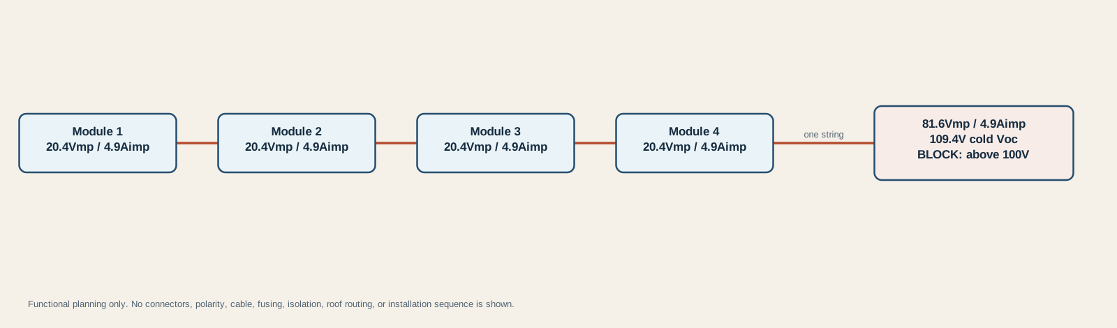
The string has 81.6 Vmp and 4.9 Aimp at STC. Its 97.2 V STC Voc may look compatible with a 100 V controller, but the tested -20 degree C condition raises corrected Voc to 109.4 V. The red result state is therefore a hard stop for this fixture, not a prompt to try the wiring and measure afterward.
The Go Power manual warns within its product context that three or more series modules can move an array beyond 60 V DC and into a higher hazard class. Exact thresholds and requirements depend on the installed system and applicable rules, but the practical lesson is sound: adding series modules changes both compatibility and hazard. Do not open or separate illuminated PV connections to investigate a rejected plan.
Four one-module strings in parallel
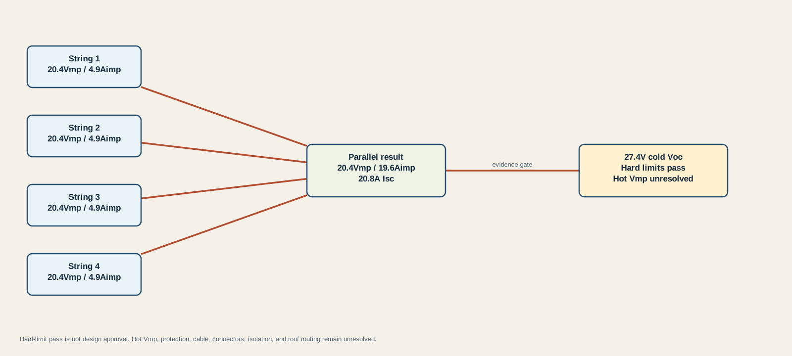
The array stays at 20.4 Vmp while four matched strings add to 19.6 Aimp. Cold Voc remains far below the example 100 V limit and Isc remains below 35 A. The diagram still ends at Hot Vmp unresolved because maximum input limits do not prove minimum operating headroom.
Four parallel branches also do not imply that any generic branch connector or fuse arrangement is acceptable. The string fault contribution, maximum series-fuse rating, combiner and connector ratings, conductor ampacity, route, temperature, voltage drop, and controller terminal limits all need exact design evidence.
Two modules per string, two strings in parallel
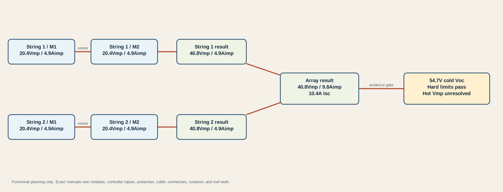
Each two-module string produces 40.8 Vmp and 4.9 Aimp at STC. Two matched strings then produce 40.8 Vmp and 9.8 Aimp. Corrected cold Voc is 54.7 V and array Isc is 10.4 A, so the recorded hard limits pass.
This may offer more voltage headroom than the one-module parallel strings while staying well below the example cold-Voc maximum. It is still not universally “best.” Two string orientations, uneven shade, mixed modules, incompatible connectors, separate tracker opportunities, or physical routing may change the preferred architecture.
Choose among electrically valid topologies
Only compare the candidates that survive all documented hard limits. Then use evidence, not slogans:
| Observed constraint | Series tendency | Parallel tendency | What must decide it |
|---|---|---|---|
| Cold climate and limited controller Voc | More series modules raise corrected Voc | Fewer series modules reduce corrected Voc | Exact Voc coefficient, local minimum design temperature, controller maximum, and required allowance |
| Hot roof and low battery-voltage headroom | More series modules raise array operating voltage | One-module strings may have less headroom | Temperature-corrected Vmp, battery charging ceiling, and exact controller startup/run range |
| Long PV route | Higher voltage and lower array current can reduce a given route’s voltage-drop burden | Higher array current can increase conductor and connection demands | A separate conductor, ampacity, terminal, protection, and voltage-drop design |
| Partial roof shade | One shaded module can constrain a series string depending on module behavior | Separate strings may isolate some effects but share voltage and protection constraints | Measured shade path, bypass-diode layout, electrical curves, orientations, and controller architecture |
| Mixed module ratings | Current mismatch can constrain series behavior | Voltage mismatch can constrain parallel behavior | Exact I-V curves, manufacturer approval, string calculation, and preferably matched modules |
| Different roof orientations | One tracker may be forced to compromise | Parallel connection does not automatically solve different operating points | Controller input architecture and manufacturer guidance for separate trackers |
| Service and fault isolation | Higher DC voltage changes hazard and disconnect requirements | More branches raise combination and protection complexity | Qualified design using exact products and applicable installation rules |
There is no universal shade winner
“Parallel is always better in shade” is too broad. The outcome depends on which cells receive shade, the module’s internal bypass-diode sections, whether shade crosses one module or several, string orientation, mismatch, and how the controller searches for the operating point. Victron’s PV shadow reference explains how blocking shade and bypass-diode grouping change module voltage and available current. A narrow roof vent shadow moving across one module is not the same problem as one entire roof side facing away from the sun.
“Series is better in low light” is also incomplete. Higher string voltage may help a controller reach its startup requirement earlier, but insufficient irradiance still limits available power. The answer must come from the exact controller range and measured or modeled roof conditions, not from voltage alone.
Create a roof shade map by time and travel use case before locking topology. If roof sections face different directions or experience materially different shade, investigate separate MPPT inputs or controllers that the manufacturer explicitly permits. Do not assume two labeled inputs are independent trackers without documentation.
Mixed modules need an explicit compatibility review
Victron’s mixed-module reference demonstrates why similar wattage is not enough. In its examples, series behavior is constrained by the lower current, while parallel behavior is constrained by the lower voltage. The reference recommends matching module size within its own system context and still checks cold Voc against the controller maximum.
For an RV retrofit, record Voc, Vmp, Isc, Imp, temperature coefficients, maximum series-fuse rating, connector family, and electrical curves for every exact module revision. If those data or manufacturer compatibility guidance are unavailable, keep the mixed array blocked. Using separate documented controller inputs can be cleaner than forcing unlike modules onto one tracker, but that decision also needs the controller manual.
Use this decision order
- Confirm exact module and controller records, battery voltage range, and environmental inputs.
- Calculate STC Vmp, Imp, Voc, Isc, and nameplate power for every candidate.
- Correct Voc for the local cold design condition and reject any topology at or above the chosen documented maximum policy.
- Check array Isc against the exact controller input limit and preserve any additional manufacturer safety factors or methods.
- Calculate hot-condition Vmp against the controller’s startup and running requirements across the battery charging range.
- Resolve controller-specific PV-power oversizing, output current, thermal derating, and clipping behavior.
- Compare only the surviving candidates using roof shade, orientations, matching, route, tracker architecture, serviceability, and the full protection plan.
- Have the exact installation plan verify connectors, conductors, fuses, disconnects, roof routing, grounding, bonding, isolation, torque, and commissioning before physical work.
Stop if a datasheet is missing, a limit belongs to another model, a corrected value reaches a hard boundary, hot Vmp is unknown, modules are electrically unmatched, the roof cannot be accessed safely, or the array cannot be isolated and verified under the exact procedure. Preserve the calculations as a planning record and use qualified RV solar service to resolve the missing evidence.
Sources and limitations
The fixture uses linear cold-Voc correction, synthetic equal modules, one local temperature example, and one documented controller example. It does not simulate an I-V curve, irradiance, bypass-diode operation, cell temperature, shade movement, snow reflection, altitude, controller tracking, thermal derating, cable loss, battery acceptance, or energy yield. It does not size an RV solar system or predict daily harvest.
Manufacturer manuals and product revisions can change. Recheck exact documentation before relying on a saved calculation. Use the RV solar sizing candidate audit to keep energy adequacy, cold Voc, array Isc, battery current, roof fit, and manual evidence as separate gates. If an installed array is producing weak or zero charge, use the RV solar not charging diagnostic to separate resource, controller, battery, and net-current evidence without turning this design page into live test instructions.
Last verified: August 28, 2026. Recalculate whenever modules, controller, battery voltage, roof layout, route, travel climate, or manufacturer documentation changes.