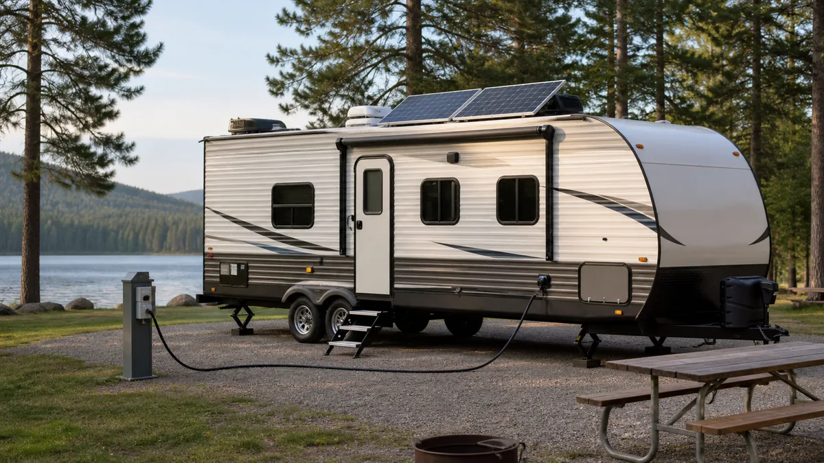
An RV normally contains two electrical systems that share some equipment but serve different loads. The house battery supplies the 12V DC side. Shore power or a generator supplies the 120V AC side. A converter connects AC to DC, and an optional inverter can connect DC back to selected AC loads.
That distinction is the fastest way to make sense of an RV electrical symptom. First identify the load that stopped working. Then identify its normal bus, the source available at that moment, and any conversion stage between them. Do not begin by guessing which component failed.
Safety boundary: This guide is a system map, not a wiring or repair procedure. You can identify operating mode, read displays, and check accessible switches or breakers according to the RV manual. Stop if you find heat, smoke, burning odor, melted parts, water intrusion, damaged shore-power hardware, repeated breaker trips, or any need to remove a 120V panel. Mains-voltage diagnosis belongs to a qualified RV electrical technician or electrician familiar with RV systems.
Start by separating the 12V DC and 120V AC systems
Start with the appliance or device, not the source. A ceiling light can work while every receptacle is dead because those loads can be on different buses. A working microwave display does not prove that the house battery is charging. An RV may also use 12V controls for an appliance whose heating element or compressor uses another energy source.
Typical load classification
| Load or function | Usual bus | What normally supplies it | Important variation |
|---|---|---|---|
| Interior LED lights | 12V DC | House battery or converter output | Some decorative or residential fixtures can differ |
| Water pump | 12V DC | House battery or converter output | The pump switch and control wiring are also part of the DC path |
| Furnace controls and blower | 12V DC | House battery or converter output | Fuel may be propane, but ignition, controls, and blower still need DC |
| Refrigerator controls | Often 12V DC | House battery or converter output | Cooling energy may be propane, 120V AC, or 12V DC depending on the model |
| Standard receptacles | 120V AC | Shore power, generator, or an inverter-fed circuit | An inverter may supply only selected receptacles |
| Air conditioner | Usually 120V AC | Shore power or generator | Some systems may be inverter-powered, but only when designed for that load |
| Microwave or electric space heater | 120V AC | Shore power, generator, or a suitably designed inverter system | These are high-power loads and can exceed the available source capacity |
Cummins distinguishes the usual 12V battery loads from 120V or 120/240V sources and notes that many lights, absorption refrigerators, and LP furnaces use 12V DC. Its RV Generator Power Basics also gives the familiar service limits: 30A service at 120V has a theoretical 3,600W maximum, while typical 50A RV service provides up to 12,000W across its two legs. Actual usable capacity still depends on the RV’s breakers, conductor design, and simultaneous loads.
A converter and an inverter solve opposite conversion problems:
- A converter or charger accepts 120V AC and produces DC for the battery and 12V system, within the design of the installed unit.
- An inverter accepts battery DC and produces AC for the circuits connected to its output. It does not create energy, and it does not automatically power every receptacle.
The RV converter versus inverter comparison separates charging, inverting, pass-through, transfer, protection, and distribution before equipment selection.
The Progressive Dynamics 7200 Series manual is an older product-specific example, not a universal RV schematic. It clearly shows the architectural idea: an AC panel distributes incoming 120V power, while the converter changes AC to DC for 12V loads and battery charging. Modern products and switching arrangements differ, so the installed manuals remain the authority for a particular RV.
Trace power in each operating mode
An operating mode is a snapshot of available sources and active conversion stages. The matrix below describes common arrangements, not a promise about a specific coach. Equipment such as solar, an inverter, an automatic transfer switch, or alternator charging may be absent.
Source-to-bus operating matrix
| Operating mode | Primary source | 12V DC bus | 120V AC bus | Conversion or charging path | What may still be unavailable |
|---|---|---|---|---|---|
| Battery only | House battery | Energized while battery, disconnect, protection, and wiring are functional | Off unless an inverter supplies selected circuits | Battery feeds the DC fuse panel directly | Most receptacles, air conditioner, microwave, and converter charging |
| Shore power connected | Campground or household AC supply | Usually energized by converter output with the battery connected to the same DC system | Energized within pedestal, cord, transfer, main-breaker, and branch limits | Converter changes AC to DC and may charge the battery | Loads above service capacity, failed branches, or circuits excluded by the installed design |
| Generator running | Onboard or portable generator connected through the approved inlet or transfer equipment | Usually like shore-power mode when the converter receives AC | Energized within generator, transfer, breaker, and wiring limits | Converter changes generator AC to DC and may charge the battery | Loads beyond generator rating or circuits not connected to generator power |
| Driving | Chassis alternator plus house battery | Energized from the house battery; charging occurs only through the installed isolation or DC-DC path | Off unless an inverter or generator is operating | Alternator source may charge the house bank through installed charging equipment | AC-only loads without an active inverter or generator |
| Solar charging | Solar array plus house battery | Energized from the battery; solar offsets loads or charges only when conditions and controller permit | Off unless an inverter is operating | Solar controller regulates array output into the battery system | AC-only loads, and any load beyond current energy and battery limits |
| Inverter operating | House battery | Energized from the battery | Only inverter-connected circuits are energized | Inverter changes DC to AC and adds battery draw | Non-inverter circuits and loads above inverter, battery, or conductor limits |
The solar row is only a system-level path. Use the RV solar series-versus-parallel guide to compare array-side voltage, current, cold Voc, controller limits, and unresolved hot-voltage evidence before treating a topology as a candidate design.
Two observations prevent common diagnostic mistakes:
- A live bus does not prove the battery is charging. Lights can run from a converter while the battery connection, charge path, or battery itself has a problem.
- An available source does not prove every branch is live. A pedestal can be energized while an RV main breaker, transfer device, GFCI, branch breaker, or individual load remains unavailable.
For a first-pass trace, write down four things: current operating mode, load that failed, bus that normally serves it, and source or converter expected to energize that bus. That short record is more useful than swapping parts. For a focused comparison of service ratings and adapter limits, continue to 30A vs 50A RV power.
Map conversion, storage, distribution, and protection
The diagram below is generated from the verified rv-electrical-system-map fixture. The same fixture defines every node, arrow, label, source record, and optional path. It is intentionally a concept map rather than a wiring schematic.
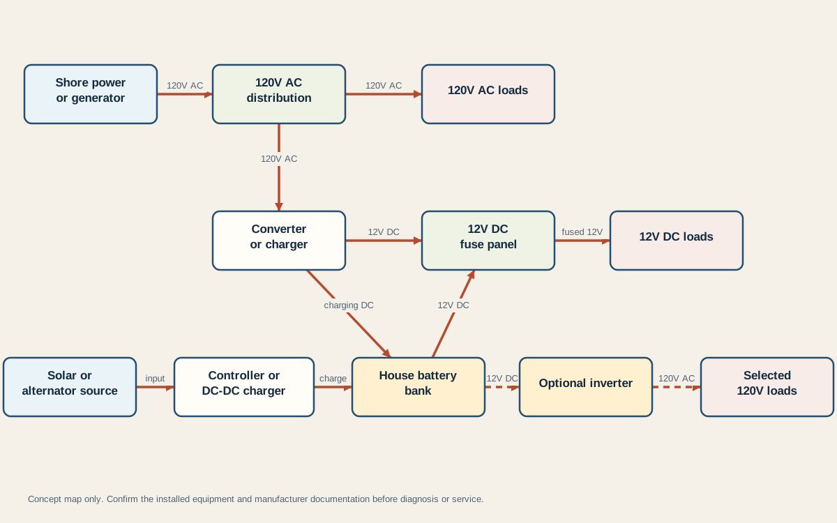
Read the map from source to load:
- Sources provide energy. Shore power and generators are AC sources. A solar array and alternator are charging sources that require the correct controller or charging path before the house battery.
- Conversion changes the form or control of power. A converter changes AC to DC. A solar controller or DC-DC charger regulates a charging source. An optional inverter changes battery DC to AC.
- Storage is the house battery bank. It stores DC energy; it is not a 120V source unless an inverter is present.
- Distribution divides power into protected branches. The AC panel uses breakers. The DC panel uses fuses or breakers appropriate to the DC circuits.
- Loads consume power. Their bus determines which source and conversion stages matter to a symptom.
When the charging source is a vehicle alternator, continue to the DC-DC charger candidate audit. It keeps verified alternator headroom, charger input current, charger output current, the two protected paths, and battery charge limits separate.
Protection is part of the power path, not an accessory added after the design. The Victron Energy Wiring Unlimited reference separates battery-bank wiring, cable selection, busbars, fuses and circuit breakers, isolation, AC distribution, and grounding into distinct design subjects. That organization supports the diagnostic rule used here: locate the source, conversion stage, distribution point, protection device, and load instead of treating the RV as a bundle of wires.
The diagram deliberately omits conductor sizes, fuse ratings, grounding and bonding details, transfer-switch internals, and equipment-specific terminals. Adding those values without the actual RV, circuit length, load, battery fault-current capability, device manuals, and applicable code would turn a safe orientation map into a misleading installation drawing.
For the omitted AC safety relationship, continue to the RV grounding and bonding guide. Its source-mode evidence map separates DC negative, chassis, neutral, equipment ground, earth, and bond ownership while keeping physical verification and changes within qualified service.
Route a symptom to the correct first test
Use this router only for safe observations. A “first test” here means identifying the affected bus and operating mode, checking an owner-accessible control described in the RV manual, or collecting evidence for a technician. It does not mean probing a live AC panel.
Symptom routing table
| Symptom | Likely scope to identify first | Safe first observation | Stop condition | Next guide in the pilot plan |
|---|---|---|---|---|
| Both 12V lights and 120V receptacles are dead | Whole-coach source or distribution problem | Record whether shore power, generator, and battery disconnect are available; check for heat, odor, or visible damage without opening panels | Any damage, burning odor, wet equipment, or uncertain source state | RV 12V power not working, then shore-power checks if the AC side is also affected |
| 12V lights and pump are dead, but receptacles work on shore power | DC distribution, converter output, battery disconnect, or battery path | Confirm several known DC loads fail and note whether the battery monitor or converter indicator is active | A fuse opens again, wiring is hot, or access requires removing a panel | RV 12V power not working |
| Receptacles are dead, but 12V lights work | 120V source, transfer, main/branch breaker, or GFCI path | Confirm the operating mode and whether all receptacles or only one group is affected | Repeated trip, damaged cord or plug, heat, water, or need to expose live conductors | RV outlets not working |
| Battery voltage or state of charge keeps falling on shore power | Converter charge path, battery connection, configuration, or battery condition | Record battery indication before and after connecting shore power and note whether DC loads remain functional | Battery heating, swelling, odor, leakage, sparking, or abnormal converter behavior | RV battery not charging on shore power |
| Only one 12V device fails | Individual DC branch, local switch, connector, or device | Test another device on the same general bus and identify the labeled branch from owner documentation | Replacement fuse opens again or wiring/device shows heat damage | RV fuse panel explained |
| Only one 120V appliance fails | Appliance, receptacle group, GFCI, or branch | Try a known operating mode and follow only the reset or breaker procedure in the RV manual | Repeated trip, heat, arcing, damaged receptacle, or exposed wiring | RV outlets not working |
If the evidence points to the 12V side, the next question is whether the entire DC bus is unavailable or only one protected branch. If it points to the 120V side, separate source availability from branch availability. If the symptom crosses both buses while connected to shore power, the converter is one possible connection between them, but it is not the only possible cause.
Record model numbers, operating mode, source status, affected loads, indicators, and the exact sequence that produced the symptom. That evidence makes the next diagnostic step narrower and safer.
When the symptom is specifically a house battery that does not appear to charge while plugged in, use the shore-power battery charging test sequence after this system-level classification.
For how sources are selected and reviewed, see the editorial policy and content process.
Last verified: August 27, 2026. Equipment topology varies by RV; confirm the installed manuals before service.