If every house 12V load is dead, first determine whether the outage occurs on battery power, accepted shore or generator power, or both. If only one light, pump, fan, or appliance control is dead while other 12V loads work, treat it as a branch-level symptom instead. This scope-and-mode split is more useful than starting with a battery, fuse, disconnect, or converter guess.
An RV can receive house DC from its battery path and, under the installed design, from a converter or charger when acceptable AC is present. One source can therefore mask a fault in the other path. Record what works in each mode before changing a switch, resetting protection, disconnecting a cable, or buying a part.
Safety and limitations: An RV battery can deliver destructive short-circuit current, and a power center can contain lethal 120V AC beside the 12V section. Owner work on this page stops at documentation, externally visible condition, and controls or indicators that the exact manuals explicitly make owner-accessible. Do not remove an energized cover, probe a live panel, disconnect a live battery cable, bridge a fuse or breaker, bypass a disconnect, upsize protection, or repeatedly reset an opening device. Stop for heat, odor, smoke, swelling, leakage, discoloration, damaged conductors, water exposure, arcing, a device that opens again, uncertain source isolation, or any access not clearly authorized by the installed manuals.
Decide whether the whole 12V bus or one branch is out
Choose at least three known house 12V loads on different functions, such as an interior light, water pump, and furnace or refrigerator control. Do not use ordinary household-style receptacles as a DC test: those are normally 120V AC unless an installed inverter supplies selected outlets. The RV electrical system overview explains that boundary.
Observe the same loads in two documented modes when the RV manuals allow the change safely:
- Battery-only state: shore cord disconnected, generator stopped, and other charge sources recorded. Use installed controls; do not remove conductors to create the state.
- Accepted-AC state: the RV has accepted a verified shore or generator source and no stop condition is present. Record solar, alternator, 7-pin, and inverter/charger state because another source can alter the result.
| Scope and mode result | What it establishes | What it does not establish |
|---|---|---|
| All sampled 12V loads fail in both modes | The symptom may involve a shared DC bus, shared return, unavailable sources, isolation, or more than one fault | It does not prove the converter, battery, or main fuse failed |
| Loads fail on battery-only but work on accepted AC | The converter-side contribution may be masking a battery-source path problem | It does not distinguish battery state, upstream protection, disconnect, connection, or return path |
| Loads work on battery-only but the behavior changes or fails on accepted AC | The battery path can support the sampled loads; the accepted-AC and converter state needs its own evidence | It does not prove the converter failed or authorize AC-panel access |
| One named branch fails while other 12V branches work in both modes | The shared source and bus can support at least the working loads; focus moves downstream toward that branch | It does not prove the branch fuse is open or the appliance failed |
| Several related loads fail, but unrelated 12V loads work | A shared subcircuit, control module, local return, or documented branch grouping may own the symptom | It does not justify assuming the printed directory is current after modifications |
| A load starts, dims, cycles, or fails only under demand | The path may have a load-dependent source, connection, conductor, protection, or return issue | A normal-looking no-load voltage does not prove adequate current delivery |
Jayco’s 2026 Class C manual is one manufacturer example: it documents a solenoid-controlled house-battery disconnect and says that solenoid must be engaged for its described house 12V system to operate. WFCO states that its converters can supply nominal 12V power without a battery. Neither statement is a universal RV topology. Your disconnect can be mechanical or controlled, may affect only selected circuits, and may interact differently with converter output.
If the symptom is only “the battery is not charging” while house 12V loads still work, use the shore-power battery charging diagnostic. This page owns loss of 12V load operation; the charging page owns source-to-battery charge evidence.
Collect owner-safe evidence before measuring
Do not start by cycling every switch or pulling every fuse. First build a record that preserves the state in which the failure occurs.
| Evidence field | Record exactly | Why it changes the path |
|---|---|---|
| RV identity | Manufacturer, model, model year, floor plan, and known electrical modifications | Disconnect behavior, branch grouping, hidden protection, and alternate sources vary by RV |
| DC equipment identity | Power-center, converter/charger, battery, battery monitor, solar controller, and disconnect model or type | Indicator logic, limits, profiles, and permitted access belong to exact equipment |
| Source state | Shore, generator, engine/alternator, tow-vehicle 7-pin, solar, inverter/charger, and battery state | An unrecorded source can mask an open path or change voltage |
| Symptom scope | Every affected and unaffected known 12V load in each operating mode | Working branches establish only their shared upstream path, not every branch |
| Timeline and load | What changed immediately before the outage and whether failure appears only when a load starts | Modifications, storage, reverse connection, overload, vibration, or water exposure can change the risk and likely path |
| Owner-visible protection | Exact directory label, indicator state, and device markings without removal unless the manual permits it after isolation | Appearance or proximity alone does not establish ownership or condition |
| Stop conditions | Heat, odor, swelling, leakage, discoloration, damaged insulation, water, arcing, or repeat opening | Any one of these ends the owner sequence |
Use the installed monitor only as one observation. The battery state-of-charge guide explains why a percentage or voltage display depends on chemistry, configuration, operating state, and measurement method. A display that wakes up does not prove the full battery-to-bus path can carry load current.
Indicators also need exact product logic. WFCO explains that some fuse-board LEDs require a load on the output circuit to illuminate when a fuse is open. It also notes that its monitoring circuit can place voltage on an output terminal even with the fuse removed, without useful current behind that indication. This is why “the LED is off” and “a meter sees voltage” are clues, not fuse verdicts.
The RV fuse-panel reference separates upstream battery protection, converter reverse-polarity protection, and DC branch fuses. If the exact RV and equipment manuals allow owner fuse replacement, follow their complete isolation procedure and preserve the specified type and rating. Jayco and WFCO both require same-type/rating replacement in their documented contexts. An opened replacement, unknown rating, inaccessible device, or need to remove a hazardous cover ends owner work. Fuse sizing for a modification is a different engineering task.
Before accepting AC for the mode comparison, use the shore-power safety check if the pedestal, cord, inlet, weather, or source condition is uncertain. A 12V symptom does not make damaged mains equipment safe.
Trace the 12V path by test node
The remaining sequence is a qualified-service framework, not an owner probe tutorial. A qualified technician uses the exact schematics and service manuals to identify accessible nodes, establish isolation, select a correctly rated and fused instrument, protect against battery fault current, and decide whether a measurement must be de-energized or energized. If those controls are unavailable, the result stays unresolved.
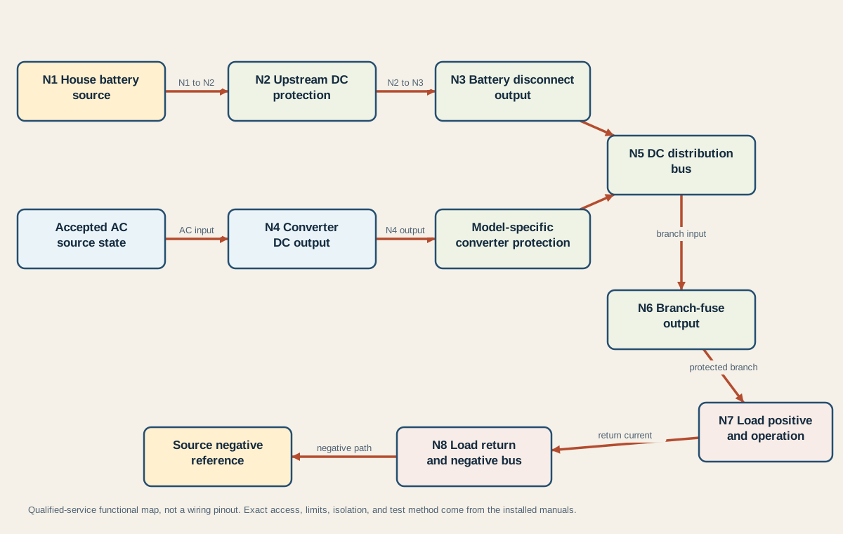
The diagram is functional. It does not show terminal positions, wire colors, conductor sizes, fuse ratings, or a universal order inside an enclosure. Use its stable IDs to keep each record reproducible:
| Node | Evidence owned by the node | Required context | Interpretation limit |
|---|---|---|---|
| N1 house battery source | Battery-terminal state under the approved test condition | Chemistry, temperature, rest/charge/load state, other sources, exact battery manual | A no-load reading does not prove capacity, health, or current delivery |
| N2 upstream DC protection output | Whether the documented battery feed continues past its source protection and connections | Exact protection type, location, isolation method, and simultaneous N1 state | An unexpected change locates a path boundary; it does not explain why protection opened |
| N3 battery disconnect output | Whether the documented disconnect path passes the battery contribution in its commanded state | Mechanical or solenoid type, control power, bypassed circuits, exact RV logic | A click or indicator does not prove the contacts carry current |
| N4 converter DC output | Converter behavior with accepted AC under the manufacturer’s specified setup | Exact model, AC input evidence, load state, profile, temperature, and manual limits | One generic target voltage cannot diagnose every converter |
| N5 DC distribution bus | The state where available source contributions reach distribution | Which sources are active and how the installed topology joins them | Expected voltage at the bus does not prove every branch or return is sound |
| N6 branch-fuse output | Whether the named branch continues past its documented protection | Correct directory, circuit state, indicator logic, fuse method, and N5 reference | Voltage from an indicator circuit can exist without useful branch current |
| N7 load positive and operation | Supply state at the load while its control requests operation | Load command, interlocks, duty state, and comparison with N6 | Supply presence does not distinguish an internal load fault from a bad return |
| N8 load return and negative bus | Return-path behavior while the same load state is preserved | Exact reference nodes, load current, chassis/negative topology, and source return | A continuity result while de-energized may not reveal a resistance problem under load |
Progressive Dynamics publishes converter-output procedures for named product families, including model-specific terminal access, AC conditions, battery isolation, output limits, and reverse-protection checks. Those steps belong only to the named products and competent service context. This map extracts the evidence pattern, not their terminal locations or numeric limits.
The return path matters just as much as the positive path. Victron’s DC wiring reference calculates voltage drop across the total positive-plus-negative conductor length and describes connection resistance, heat, protection, and the difficulty of tracing loose negative connections. A technician should therefore preserve the same source and load state while comparing both delivery and return. Replacing a positive fuse cannot repair a poor return.
Interpret the first unexpected node
Interpret a test as a boundary between the last node that behaves as the exact manuals expect and the first node that does not. “Expected” must include node pair, source state, load state, time, temperature when relevant, instrument method, and product-specific limit. If any field is missing, record UNRESOLVED instead of naming a failed component.
| Last expected / first unexpected evidence | Bounded interpretation | Next owner |
|---|---|---|
| N1 itself is outside the battery manual’s expected state | Battery state, monitor interpretation, terminal interface, or battery condition needs separate evidence | Start with RV battery state of charge; use manufacturer-directed battery testing before a health verdict |
| N1 behaves as expected but N2 does not under the same approved state | The boundary is in the upstream battery protection or its connections/path | Qualified DC service using the exact RV protection documentation; do not bypass or upsize |
| N2 behaves as expected but N3 does not in the commanded state | The battery-disconnect path, solenoid/control logic, or connections require exact-model diagnosis | RV manufacturer documentation or qualified RV electrical service |
| Battery path supports loads, but N4 is unexpected with accepted AC | The converter contribution or its AC input/protection/configuration remains unresolved | RV battery not charging on shore power owns that sequence |
| N1 or N4 is expected, but N5 is not | The join to distribution, converter-specific protection, common bus, or shared return needs inspection | Exact power-center/converter documentation and qualified service |
| N5 is expected and one branch becomes unexpected at N6 | The named branch protection, directory assignment, contact, or immediate branch path owns the boundary | RV fuse panel explained plus the exact panel/RV manual |
| N6 is expected but N7 or load operation is not | The branch conductor, switch, interlock, local protection, connector, or equipment may own the symptom | Exact appliance and RV circuit documentation; no automatic appliance-failure verdict |
| Positive delivery is expected but N8 return behavior is not | The return conductor, connection, negative bus, or documented chassis bond path owns the boundary | Qualified DC service; preserve load state and exact reference nodes |
| Every no-load node appears expected, but the fault returns under demand | A source, connection, conductor, protection device, load, or return may be unable to support current | Controlled load-dependent diagnosis by qualified service; do not tighten to a guessed torque |
| A fuse or breaker opens again, or any stop condition appears | An active fault or unsafe condition remains | De-energize using approved controls and obtain qualified service; no further reset or replacement cycle |
This matrix does not diagnose by distance alone. An unexpected N4 value can come from missing AC input, configuration, protection, load, instrument setup, or converter behavior. An unexpected N6 value can come from the device, its contact, indicator topology, or branch assignment. A normal N7 positive reading with no operation can still leave the return or equipment unresolved.
The useful handoff is an evidence packet: exact RV and component identities, manuals, source states, affected and unaffected loads, load state, N1-N8 records, last expected node, first unexpected node, photographs of owner-visible labels, and every stop condition. That is enough to replace random parts with a bounded next test while preserving the possibility that the evidence does not yet support a verdict.