Deterministic candidate audit · fixture 1.0.0
RV inverter candidate checker
Audit one inverter you already selected. Synthetic defaults demonstrate QA and are not appliance, inverter, battery, cable, fuse, or installation recommendations.
Overall candidate status
Needs evidenceNumbers alone cannot approve this candidate.- Running headroom
- —
- Surge fit
- —
- Arithmetic DC-current floor
- —
- Documented candidate DC design current
- —
- Battery current available
- —
- Verified DC-path limit
- —
Decision policy and fixture cases
Any failed gate rejects. Otherwise any unknown produces needs-data. Candidate-only requires all twelve gates and remains a planning audit, not approval.
- all-gates-pass: expected candidate-only
- continuous-load-fails: expected reject
- surge-watts-fail: expected reject
- surge-duration-fail: expected reject
- dc-basis-fail: expected reject
- battery-current-fail: expected reject
- dc-path-fail: expected reject
- load-evidence-missing: expected needs-data
- waveform-evidence-rejects: expected reject
- multiple-evidence-missing: expected needs-data
- equal-boundaries-pass: expected candidate-only
- missing-numeric-input: expected needs-data
Use this checker to audit one inverter candidate that you already selected. It does not recommend a 1,000W, 2,000W, or 3,000W class. The same candidate must fit the simultaneous AC load, documented startup event, design temperature, battery/BMS, complete DC path, waveform requirements, and installed AC system.
Candidate-only means the twelve entered gates agree under this fixture. It does not prove that the entries describe the RV, predict runtime, approve an appliance, select protection, or authorize installation.
Safety and limitations: An inverter joins a battery path capable of destructive fault current to hazardous AC output. Do not open energized equipment, alter battery terminals, install cable or protection, connect an inverter to RV branch wiring, modify a transfer device, or change neutral/ground bonding from this page. Exact inverter, battery, RV, and appliance manuals plus applicable qualified practice control the work.
Audit one inverter candidate
The defaults are synthetic QA data: 1,200W of simultaneous running load, a 2,200W startup event lasting one second, and a candidate documented for 1,600W continuous at the design temperature plus 3,000W for three seconds. The DC planning inputs are 11.5V at the inverter, 90% documented efficiency, 175A candidate DC design current, a 220A bank ceiling, 20A of other DC load, and a 200A verified DC-path limit.
These are not typical ratings. All six evidence selectors begin not verified, so the example cannot display candidate-only until the reader deliberately supplies and accepts the evidence.
Collect the inputs in this order:
- List only AC loads that can operate together. Record input watts at the relevant mode, not output heat, cooking, or motor ratings.
- Identify the startup event that can occur while those running loads remain active. Obtain both watts and duration from applicable equipment evidence or a qualified measurement.
- Copy the candidate’s continuous watts at the design temperature, peak watts, peak duration, input-voltage range, efficiency basis, and manufacturer DC design requirements.
- Record exact bank continuous and peak-duration discharge limits, configuration, BMS behavior, temperature, state, and other DC loads.
- Audit the complete battery-to-inverter path and the inverter-to-load AC architecture separately.
Six numeric gates test continuous load, surge watts, surge duration, the DC-current arithmetic floor, available battery current, and the verified DC-path limit. Six evidence gates preserve load, inverter, battery, DC path, waveform, and AC-system ownership. Any failed gate rejects. If none fails but one is unknown, the result remains needs evidence. Only twelve passes return candidate only.
The result intentionally resists a common shortcut: a battery bank containing many amp-hours may provide long energy storage yet still have insufficient instantaneous discharge current. Conversely, a high-current bank may support the instant but not the desired runtime. Use the battery runtime calculator for the separate energy-to-time question.
Build the AC load and surge envelope
Size from the loads that may operate at the same moment, not every appliance owned and not daily watt-hours. A 1,200W microwave and 1,000W coffee maker used separately create a 1,200W running envelope. If they can run together, the envelope is 2,200W before other active loads.
For every load, preserve:
| Field | Evidence needed | Common mistake |
|---|---|---|
| Running input watts | Nameplate, manual, or suitable measurement in the intended mode | Using cooking output or a generic appliance table |
| Simultaneous state | An explicit operating scenario | Summing everything owned or assuming users will never overlap loads |
| Startup watts | Manufacturer data or suitable captured event | Applying a generic motor multiplier |
| Startup duration | Time attached to the same event and condition | Comparing a momentary peak with a longer required event |
| Waveform, voltage, frequency | Appliance and inverter documentation | Assuming watts alone prove compatibility |
Victron’s current Inverter Smart specifications list continuous watts at multiple temperatures separately from peak power. The exact values are product examples, not sizing rules for another model. The lesson is that a headline VA or room-temperature number cannot substitute for continuous watts under the intended ambient and installation condition.
The operation manual explains that motor or pump inrush can exceed the overcurrent trip behavior and cause voltage reduction, shutdown, and restart attempts. Passing a peak-watt comparison therefore requires the candidate duration to be at least the required startup duration. A label saying only “surge 3000W” has missing evidence if it does not define the condition or duration relevant to the load.
Equality passes the fixture’s numerical continuous and surge gates. It creates no temperature, tolerance, aging, voltage-drop, or manufacturer-required margin. If an exact manual requires reserve, derating, or a different comparison, that requirement controls the inverter evidence gate.
The converter-versus-inverter guide identifies whether the equipment must only invert or also charge and transfer AC. Do not silently turn a plain-inverter sizing task into an inverter/charger or whole-RV transfer design.
Verify the battery and DC path
The tool computes an arithmetic floor only as a sanity check:
DC current floor = candidate continuous W ÷ (minimum DC voltage at inverter × efficiency)
At the synthetic defaults:
1,600 W ÷ (11.5 V × 0.90) = 154.59 A
The entered documented candidate DC design current is 175A, so it is above that floor. This does not prove 175A is correct. The exact manufacturer may specify current, cable, fuse, voltage-drop, and installation requirements using a different efficiency, tolerance, overload policy, low-voltage threshold, or design method. If the documented input is below the arithmetic floor, the candidate is internally inconsistent and rejects. If it is above, the manual basis still owns the value.
The fixture then subtracts other simultaneous DC loads from the bank ceiling:
available battery current = bank maximum continuous discharge − other simultaneous DC loads
The default yields 220A − 20A = 200A. The 175A design current fits numerically, as it also fits the 200A path limit. Those are two independent gates. The bank gate cannot approve cables or protection; the path gate cannot prove battery/BMS capability.
Battle Born’s current 100Ah battery manual publishes separate continuous, 30-second peak, and shorter surge discharge data for one exact model. This supports the need for time-matched evidence; those values must not be copied to another battery or multiplied across a bank unless its manual permits the exact configuration and current sharing.
Victron’s installation manual makes battery distance, voltage loss, cable, fuse, mounting, airflow, and temperature product-specific. Its operation guidance also links low-voltage and high-ripple shutdowns with battery state and DC connections. The calculator cannot observe connection resistance or current sharing, so a numerical pass never replaces physical-path evidence.
Use the wire and voltage-drop checker and fuse candidate audit only after the exact circuit current and manual constraints are known. Each tool can reject its own candidate; neither supplies an inverter recommendation. The battery bank topology guide explains why total amp-hours alone do not prove current sharing or compatibility.
Map the five evidence owners
The deterministic visual uses the same fixture as the checker:
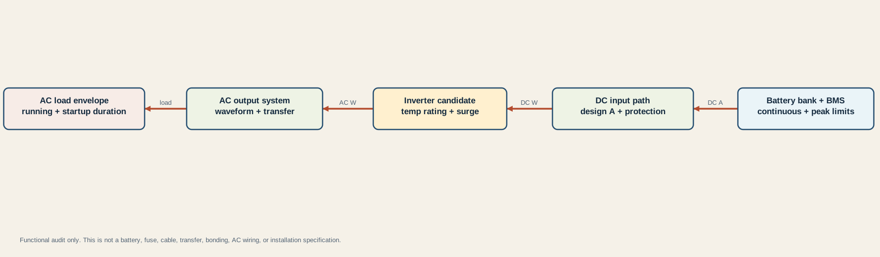
Read it from the battery toward the loads:
- Battery bank and BMS: exact configuration, continuous and peak-duration current, voltage window, temperature, state, internal protection, terminals, and permitted parallel behavior.
- DC input path: conductor and terminal limits, protection and interrupt capacity, isolation, route, temperature, voltage drop, connection quality, and manufacturer requirements.
- Inverter candidate: continuous watts at ambient, peak watts and duration, DC input range, efficiency basis, no-load demand, cooling, mounting, waveform, protection behavior, and settings ownership.
- AC output system: output voltage and frequency, branch protection, receptacles or selected circuits, transfer behavior, source isolation, neutral handling, equipment grounding, and bond ownership.
- AC load envelope: simultaneous running input watts, startup event and duration, waveform sensitivity, operating mode, and observed behavior.
The arrows are functional power boundaries. They are not terminal, polarity, cable, fuse, receptacle, transfer, neutral, or grounding instructions. The Progressive Dynamics PD1200 guide demonstrates why an RV inverter with transfer behavior has model-specific AC, neutral, and source relationships. Do not transfer its topology to another product.
The grounding and bonding guide separates DC negative, chassis, equipment grounding, neutral, earth, and source bond ownership. The fuse-panel guide identifies distribution functions without claiming that every existing branch is inverter-fed.
Preserve evidence and stop before installation
Save a candidate packet another reviewer can reproduce:
| Owner | Minimum record |
|---|---|
| Loads | Exact equipment, mode, input watts, simultaneous scenario, startup watts and duration, waveform/voltage/frequency requirements, evidence source and date |
| Inverter | Model and revision, continuous W at design temperature, VA/crest limits where applicable, peak W and duration, DC input range, efficiency basis, output specification, derating, cooling, mounting, settings, manual |
| Battery | Exact models and topology, continuous and peak-duration discharge, temperature and voltage limits, BMS behavior, state, other DC loads, terminals, manufacturer configuration rules |
| DC path | Endpoints, full route, conductor and terminal identity, ampacity basis, voltage drop, protection and interrupt basis, isolator, temperature/bundling, torque/inspection requirements |
| AC system | Connected circuits, output protection, transfer architecture, shore/generator interaction, waveform, neutral and grounding behavior, bond ownership, applicable requirements |
Stop if running watts are generic; if the startup event lacks duration; if the inverter rating belongs to another voltage, temperature, or model; if VA is treated as watts without product evidence; or if efficiency is a guessed universal percentage.
Also stop when bank discharge current is inferred from amp-hours, when parallel batteries are assumed to share perfectly, when BMS peak duration is shorter than the load event, when voltage is measured only at resting battery terminals, or when the DC path limit omits a conductor, terminal, fuse, holder, switch, connection, or environmental condition.
Candidate-only is not permission to connect the inverter to a receptacle or RV panel. A transfer or pass-through system can change source isolation, energized circuits, neutral behavior, and bonding ownership. The shore-power safety check defines owner-safe external observations; the outlet diagnostic prevents dead receptacles from becoming an invitation to open energized AC equipment.
Preserve failed and unknown gates rather than increasing the inverter rating. A larger enclosure can raise battery current, cable and protection demands, idle consumption, heat, and installation complexity while leaving waveform, startup duration, transfer, or AC-output problems unresolved.