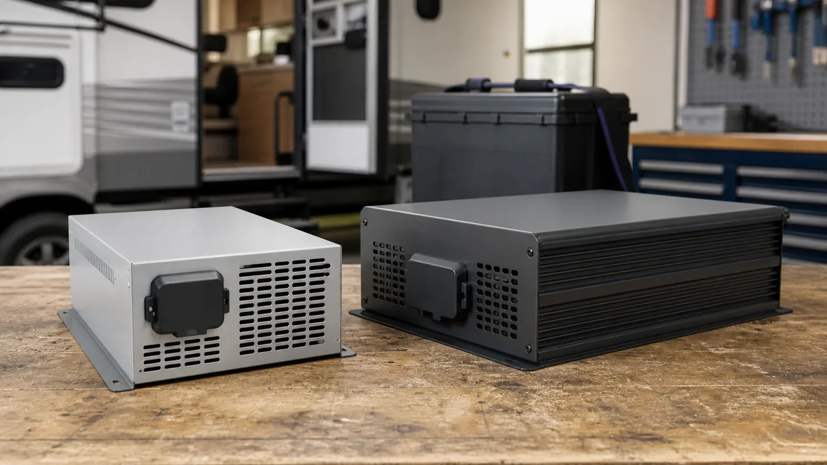
An RV converter and an RV inverter move power in opposite directions. A converter or converter/charger accepts an external AC source and produces DC for the 12V system and battery charging. An inverter accepts stored DC energy from the battery and produces AC for the loads connected to its output.
When the question is how long a battery can support an inverter-fed load, use the RV battery runtime calculator after identifying the actual load and battery limits.
An inverter/charger combines those conversion directions with a charger and, in many products, an AC transfer function. The enclosure may be combined, but the functions remain separate. The exact manual must show which functions, ratings, circuits, and switching behavior a particular model provides.
If the 12V and 120V sides are still unclear, start with the RV electrical system overview. It establishes the source, bus, distribution, and load vocabulary used below.
Safety boundary: This comparison helps identify functions and planning inputs. It is not an installation procedure. Inverter and inverter/charger work can involve high battery fault current, large DC conductors, hazardous AC voltage, transfer switching, and source-dependent bonding. Do not open energized equipment or modify AC wiring from this generic guide. Use the exact RV and equipment manuals and qualified help where required.
Converter, inverter, and inverter/charger at a glance
The shortest correct answer is based on energy direction:
- Converter or converter/charger: AC in, DC out. It supplies the DC system and charges a compatible battery within its documented limits.
- Inverter: DC in, AC out. It draws from the battery to supply the AC loads connected to it.
- Inverter/charger: AC and DC connections support charging in one mode and inverting in another. An internal transfer function may pass an acceptable AC source to the output, but its behavior and ratings are model-specific.
Function comparison
| Function or property | Converter or converter/charger | Plain inverter | Inverter/charger |
|---|---|---|---|
| Normal conversion direction | External AC to DC | Battery DC to AC | AC to DC while charging; DC to AC while inverting |
| Typical input | Shore or generator AC | House-battery DC | External AC plus house-battery DC |
| Typical output | DC bus and battery charge path | Dedicated receptacle or selected AC circuits | AC output, battery charge path, and sometimes pass-through AC |
| Charges the house battery from AC | Yes, when the charger and battery are compatible | No | Yes, within the configured charger limits |
| Produces AC from the battery | No | Yes | Yes, when inverter mode is enabled and conditions permit |
| Transfers external AC to its output | Not normally a converter function | Not normally a plain-inverter function | Common, but the exact transfer topology and rating require the manual |
| Determines AC and DC branch protection | No; protection and distribution are separate functions | No; protection and distribution are separate functions | No; combined equipment still needs the protection and distribution specified by its manual |
| Proves every outlet is powered | No | No | No; only circuits connected through the installed output path can be energized |
Progressive Dynamics’ PD4600 converter-output guide shows a manufacturer example in which shore AC enters a converter/charger, the converter supplies DC distribution and accessories, and the battery is connected to the charging/DC system. The exact output behavior and battery profile remain model-specific.
Victron’s inverter/charger function overview describes a combined enclosure as an inverter, battery charger, and automatic transfer function. That is a description of inverter/charger architecture, not evidence that every product called an inverter includes charging or transfer.
Names that cause avoidable confusion
In RV discussions, “converter” often means a 120V AC to nominal-12V DC converter/charger. Electronics catalogs also use “DC-DC converter” for a different function, such as changing one DC voltage to another. The complete product name and its input/output ratings matter more than the shortened noun.
A power center can contain an AC breaker section, DC fuse section, and converter section in one assembly. That does not make the converter an inverter. Likewise, an inverter may include an AC receptacle or transfer relay without becoming the RV’s DC distribution panel.
Follow the direction of power
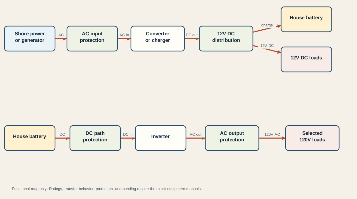
The fixture-driven diagram separates the two paths. It shows functional boundaries only, not terminal locations, conductor sizes, fuse ratings, transfer wiring, or grounding and bonding details.
Converter mode: external AC supports the DC system
With acceptable shore or generator power present, AC passes through the installed input protection to the converter/charger. The unit produces DC. That output can support the 12V distribution bus and charge the battery, subject to the converter’s current limit, charging behavior, wiring, and battery compatibility.
Three conclusions follow:
- Working 12V lights on shore power do not prove the battery is healthy or receiving the intended charge.
- A converter does not normally make 120V receptacles work. Those receptacles depend on the AC source and AC distribution path.
- A charger label does not prove compatibility with every battery chemistry, voltage, capacity, temperature condition, or manufacturer limit.
Inverter mode: the battery supports selected AC loads
In battery mode, stored DC passes through the required DC protection and conductor path to the inverter. The inverter produces AC, which then requires the output protection and distribution appropriate to the installed design. Only connected loads receive that output.
An inverter does not recharge the battery from its own AC output. A design that unintentionally routes inverter output back into a charger input creates a wasteful loop and may conflict with transfer or protection requirements. Source selection must prevent unintended backfeed and must follow the exact equipment documentation.
Battery energy, inverter efficiency, continuous and surge ratings, waveform requirements, battery-management limits, conductor capability, voltage drop, and protection all constrain usable AC power. A wattage label alone is not an installation decision.
Inverter/charger modes: one enclosure, several states
A combined unit can behave differently as source conditions change:
| Operating state | External AC | Charger function | Inverter function | AC output |
|---|---|---|---|---|
| Acceptable shore or generator source | Present and accepted | Can charge within configuration and limits | Usually not creating the primary output waveform | Often passes external AC through, within transfer limits |
| External AC absent | Unavailable | Cannot charge from that AC source | Can draw from the battery when enabled | Supplies only the connected output circuits within inverter limits |
| Charger-only mode | Present | Enabled according to configuration | Disabled | Product-specific pass-through behavior must be confirmed |
| Off, fault, or rejected input | Variable | May be unavailable | May be unavailable or may continue, depending on state and model | Cannot be inferred without indicators and the manual |
Victron’s AC wiring reference treats AC distribution, breakers, bypass arrangements, inverter/charger wiring, and grounding as distinct design subjects. This is why the phrase “it has a transfer switch” is not enough to determine which circuits are supplied or how a fault should be diagnosed.
Choose the function your RV actually needs
Do not begin with a brand or wattage. Begin with a missing function, then prove whether the RV already has it.
Function-first decision table
| Your actual task | Function to verify or add | Evidence required before a decision | What this does not decide |
|---|---|---|---|
| Charge the house battery from shore or generator power | Compatible AC-to-DC charger, often the existing converter/charger | Exact converter model, charge profile, DC output rating, battery manual, wiring and protection | Whether you need off-grid AC power |
| Run selected 120V devices without shore or generator power | Inverter function | Simultaneous running load, startup/surge data, waveform requirement, battery voltage and energy, BMS limits, DC path capability | Whether the battery can also be charged from AC |
| Charge from AC and automatically support selected AC circuits when the source disappears | Inverter/charger plus verified transfer design | AC input/output ratings, transfer rating and behavior, charger profile, inverter limits, circuit ownership, bonding behavior | Whether every RV circuit belongs on the backed-up output |
| Operate only 12V DC loads off-grid | No inverter function may be necessary | Confirm that every required load is genuinely DC and that charging sources meet the energy need | Converter compatibility or shore charging performance |
| Add an inverter while retaining an existing converter | Separate inverter may be possible | Prevent unintended AC loops or backfeed; identify dedicated versus transferred circuits; verify both manuals and all protection | A universal wiring layout |
| Replace a converter with an inverter/charger | Combined functionality may replace some equipment roles | Document old and new functions, battery compatibility, AC transfer topology, DC path, physical environment, and applicable code | Permission to remove unrelated distribution or protection |
Minimum identification record
Before buying, configuring, or troubleshooting, record:
- Manufacturer, exact model, and manual revision for the existing converter, inverter, transfer switch, and power center.
- House-battery nominal voltage, chemistry, capacity, BMS limits, and the battery manufacturer’s charging requirements.
- The AC loads that must operate together, including documented startup or surge behavior and waveform requirements.
- Which receptacles or branches are connected to shore power, generator power, inverter output, or a transfer device.
- Charger current and voltage behavior, inverter continuous and surge limits, AC pass-through rating, and operating modes.
- Required DC and AC protection, conductor sizes, connection torque, ventilation, mounting, and grounding or bonding instructions from the exact manuals.
If any decisive value is missing, the result is needs data, not a guessed product size. Use the RV inverter sizing candidate audit to keep running load, startup duration, DC current, battery/BMS, path, waveform, and AC-system evidence separate. For a named LiFePO4 pair, the next compatibility step is the converter and lithium-battery compatibility audit, which compares the exact charger’s behavior with the exact battery requirements.
This page owns component roles and function selection. It does not own inverter wattage calculation, battery-runtime estimation, lithium charging compatibility, or wiring design. Keeping those tasks separate prevents one generic comparison from becoming unsafe installation advice.
Last verified: August 27, 2026. Product functions and transfer behavior are model-specific; verify the current manufacturer manuals.