
An RV battery monitor sees only the current that crosses its shunt. It normally reports net battery current, not the output of each charger or the consumption of each load. Its state-of-charge percentage is a separate calculated estimate that depends on complete current capture, correct settings, and synchronization.
That distinction resolves many apparently contradictory readings. A solar controller can report charging while the shunt correctly reports discharge because the RV’s simultaneous loads are larger than the solar output. A monitor can also show plausible amps while its percentage drifts because one path bypasses the shunt or the state-of-charge settings are wrong.
Safety and limitations: This guide supports documentation and interpretation, not installation. Battery banks can deliver destructive fault current. Do not remove a battery cable, move a return, open a shunt cover, loosen a terminal, perform zero-current calibration that requires disconnection, or work on an energized system from this page. Stop for heat, odor, corrosion, damaged insulation, loose hardware, unknown modifications, exposed conductors, uncertain isolation, or any task outside the exact manual and your qualifications.
Trace the shunt measurement boundary
A shunt is a product-specified low-resistance measuring element. Its compatible monitor reads a small voltage signal across that element and converts the signal to current. The shunt’s current and signal ratings, monitor configuration, terminals, and installation limits must match the exact product; its appearance does not establish compatibility.
For coverage, the important boundary has two functional sides:
- The battery side is the counted connection toward the monitored battery bank.
- The system side collects the intended load returns and charging returns.
- The shunt is the only intended current path between those two sides.
Victron’s current SmartShunt installation manual explicitly places loads, inverters, battery chargers, solar chargers, and other charge sources after the shunt on the system side. Renogy’s RBM500 manual and Bogart’s TM-2030 manual express the same measurement-boundary principle within their own product terminology.
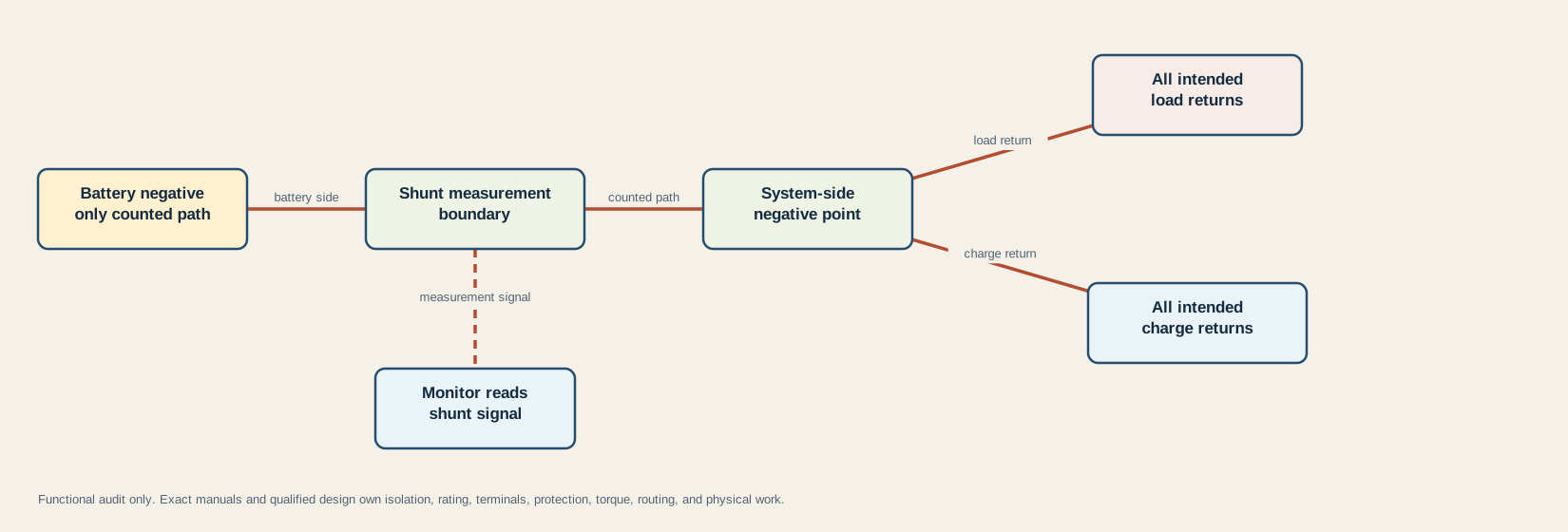
The diagram is functional, not a physical wiring plan. “All intended” includes paths that are easy to overlook: converter charging, solar charging, an inverter/charger, DC-DC charging, a chassis return, equipment connected directly near the bank, and later modifications. Whether a chassis connection belongs at a particular point is a system-design question; use the RV grounding and bonding guide to keep the function names distinct.
One direct return on battery negative or the battery side can bypass measurement:
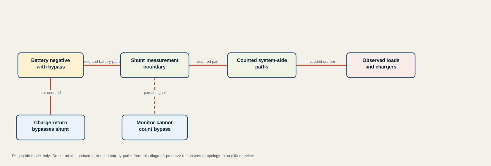
In that state, the bypassed charger can change real battery current while the monitor never counts that contribution. A bypassed load creates the opposite accounting omission. The monitor may still display voltage, communicate normally, and show current from the paths that do cross the shunt. Those signs do not prove complete coverage.
Audit each path by identity rather than cable color or proximity:
| Path record | Evidence to preserve | What the record establishes |
|---|---|---|
| Monitored bank | Exact batteries, topology, and which bank the monitor represents | The intended storage boundary, not compatibility or capacity health |
| Shunt and monitor | Manufacturer, model, revision, shunt rating, signal rating, and exact manual | Product identity and documented interpretation rules |
| Battery side | Owner-safe photo or existing diagram showing every connection at that boundary | Whether an obvious extra path may bypass measurement |
| System side | Documented load, converter, solar, inverter, DC-DC, chassis, and accessory returns | Which intended paths should be counted |
| Later modifications | Installer records, added equipment, and dated photos | Whether the topology may differ from the factory diagram |
For a multi-battery bank, do not infer the measurement boundary from one case or terminal. First verify the bank topology with the series-versus-parallel guide, then use the exact monitor and battery documentation. This page deliberately publishes no terminal stack, cable route, protection location, shunt rating, or torque.
Interpret net battery current
Under the fixture’s declared sign convention, positive means net current into the battery and negative means net current out. For paths that cross the shunt:
measured net current = observed charging current - observed load current
The exact display may use different labels or signs, so confirm its manual. Victron’s troubleshooting chapter states that charging should display positive and discharging negative for that product; reversed power-path orientation inverts those readings.
These synthetic cases are generated from rv-battery-monitor-shunt-topology.json. They explain accounting only and are not expected RV currents:
| Case | Counted charge | Counted load | Bypass charge/load | Shunt display | Physical battery net | Meaning |
|---|---|---|---|---|---|---|
| Charge exceeds load | 20A | 8A | 0A / 0A | +12A | +12A | Complete topology; battery receives net charge |
| Charger active, net discharge | 5A | 7A | 0A / 0A | -2A | -2A | Charger output is real, but loads are larger |
| Balanced net zero | 8A | 8A | 0A / 0A | 0A | 0A | Zero net does not mean that every source and load is off |
| Charge bypasses shunt | 0A | 3A | 10A / 0A | -3A | +7A | Display misses the direct battery-side charge return |
| Load bypasses shunt | 5A | 0A | 0A / 9A | +5A | -4A | Display misses the direct battery-side load return |
The last two physical-net values are available to the fixture because the synthetic bypass current is known. In a real RV, the purpose of the audit is to discover that the display is incomplete; do not invent the missing amps.
This also explains a frequent solar misunderstanding. A solar controller reports its own output under its own measurement conditions. The shunt reports what remains at the battery boundary after simultaneous counted loads. If the controller shows positive output while the monitor shows net discharge, use the solar no-charge evidence guide to preserve resource, controller, battery, and net-current evidence instead of declaring either device failed.
A near-zero display has multiple possible meanings: balanced counted current, genuinely low current, a configured current threshold, an offset, unavailable resolution, or incomplete coverage. Do not use one zero reading as proof of isolation. Likewise, do not perform a zero-current calibration merely because the display is not exactly zero; the exact procedure may require physical disconnection and belongs to the manual and qualified service.
Separate current from state of charge
Current is an instantaneous measurement at the shunt boundary. State of charge is an estimate that integrates current over time and applies product-specific assumptions. Victron’s operation chapter identifies capacity, charge efficiency, Peukert behavior, charged voltage, tail current, and detection time among the concepts used by its monitor. Other products expose different names and models.
Synchronization provides a known full-state reference for the calculation. It does not repair a bypass, prove actual capacity, or make incorrect settings true. Never copy one manufacturer’s example charged voltage, tail current, Peukert value, efficiency, or discharge floor into another battery and monitor pair.
| Observation | First evidence question | Plausible categories | What it does not prove |
|---|---|---|---|
| Charge and discharge signs appear reversed | Does the exact manual’s sign convention match the observed direction? | Reversed shunt orientation, swapped functional sides, mislabeled observation | Failed battery or monitor |
| Amps respond plausibly but SoC drifts | Are all paths counted, and are settings and synchronization documented? | Bypass, wrong capacity or efficiency model, missed full synchronization | Correct topology merely because amps move |
| SoC remains at or near 100% | Does discharge current appear with a documented load state? | Inverted direction, bypassed load, premature synchronization, stale estimate | A full or healthy battery |
| SoC never reaches 100% | Did the real battery reach its documented full conditions, and could the monitor recognize them? | Incomplete charge, charged-condition mismatch, missing current, synchronization issue | A defective charger from percentage alone |
| Controller shows charging while shunt shows discharge | What were simultaneous loads, and do both paths cross the boundary? | Loads exceed charger output, bypass, different timestamps, measurement scope | Contradictory devices |
| Current reads zero | Were charge and load balanced, below threshold, or outside coverage? | True zero, net zero, threshold, offset, bypass, unavailable resolution | De-energization or no current anywhere |
The RV battery state-of-charge guide compares shunt estimates with voltage, battery-management data, and chemistry-specific evidence. A monitor percentage is useful only inside that evidence hierarchy. It is not a direct capacity test, state-of-health test, cell-balance report, or permission to continue discharging.
Do not confuse charger stage with battery percentage. The converter charging-stage guide explains why a converter label or mode must be interpreted through the exact charging algorithm and battery conditions. A monitor’s synchronization logic is another model, not a duplicate charger verdict.
Audit the monitor without rewiring
Start with a snapshot that can be reviewed without disturbing the battery path:
| Snapshot field | Record |
|---|---|
| Identity | RV, battery bank, monitor, shunt, firmware if shown, and exact manual revision |
| Time and mode | Timestamp; shore, generator, solar, alternator, and inverter states as already displayed or documented |
| Monitor values | Voltage, current, power, SoC, time remaining, alarms, and whether values are live, cached, or unavailable |
| Charger values | Output current, stage, limit, fault, and timestamp from each safely accessible display or app |
| Loads | Known major loads that were already operating; do not create a test load from this page |
| Topology evidence | Existing diagrams, closed-panel photos, labels, installer records, and any suspected direct battery-side path |
| Configuration | Battery capacity, chemistry/profile, charged conditions, efficiency, Peukert setting where applicable, threshold, and last known synchronization |
| Change history | Battery, charger, inverter, solar, DC-DC, chassis, or monitor work since the last reliable reading |
Compare only readings from the same operating snapshot. A controller value from noon and a shunt value after clouds or a load change do not form a valid subtraction. Mark an unavailable value UNAVAILABLE; do not backfill it with a product-page default or an assumed “typical” RV load.
Use these bounded outcomes:
- Coverage supported: every intended path is documented on the system side, no bypass is evident, direction matches the exact manual, and readings reconcile within their stated scope. This supports interpretation, not installation approval.
- Bypass suspected: a return appears on battery negative or the battery side, or physical behavior changes without a corresponding monitor response. Preserve evidence and route physical confirmation to qualified service.
- Direction unresolved: sign changes conflict with the exact manual or topology. Do not correct the sign in software merely to make the display look plausible.
- Configuration or synchronization review: current is credible but SoC behavior conflicts with documented capacity, charged conditions, or synchronization history. Review exact battery and monitor requirements together.
- Insufficient evidence: identities, paths, timestamps, safe access, or settings are incomplete. Keep the result unresolved.
Stop before any action that changes a high-current path. Bogart’s current TM-2030 manual explicitly assigns shunt installation to someone familiar with safe electrical practices, and the Victron and Renogy manuals contain model-specific connection, rating, and setup requirements. Those sources verify why the boundary exists; they do not make this page an installation procedure.
The audit is complete when another reviewer can identify what the monitor counts, reproduce the net-current comparison, distinguish current from SoC, and list every unresolved assumption. It is not complete merely because the percentage looks reasonable.
Sources and limitations
The topology and arithmetic cases are deterministic. Real accuracy depends on exact product ratings, calibration, temperature, connections, firmware, battery behavior, settings, and complete current capture. This guide does not select a shunt, size a conductor or fuse, establish compliance, diagnose battery health, or verify physical workmanship.
Last verified: August 29, 2026. Recheck the exact monitor, shunt, battery, and charging-source manuals after any product, firmware, or system change.