
An RV solar controller showing 0 A does not, by itself, prove that the controller has failed. It may be night, shaded, below the controller’s required PV-to-battery voltage margin, already limiting a full battery, disabled by a setting or BMS, or producing power that active loads consume before it reaches the battery as net charge.
Start with one time-aligned snapshot from closed displays or apps. Separate what the controller reports at its PV input, what it reports at its output, and what a correctly installed whole-bank monitor reports at the battery. The first unexpected or unknown state narrows the problem; it does not automatically identify a failed part.
Safety and limitations: Solar panels can produce DC voltage whenever illuminated. This guide stays with visual observations, installed displays, apps, and documentation. It does not authorize roof access, opening a controller or electrical compartment, separating PV connectors, bypassing a controller, changing wiring, or probing energized terminals. Exact manuals own model thresholds, isolation order, protective equipment, test points, torque, and reset procedures. Stop and use qualified RV solar service when the missing evidence requires physical PV or battery-path work.
Classify the no-charge symptom before testing
Choose the row that matches what you actually observed. These symptoms answer different questions.
| Symptom class | What you observed | What it does not prove |
|---|---|---|
| No solar input evidence | The controller/app shows no PV input, a night state, or no solar icon in daylight | It does not distinguish shade, resource, array configuration, an open path, display logic, or controller input failure |
| PV input present, output zero or low | The controller sees PV but reports no or limited charge output | It does not distinguish a full battery, insufficient voltage headroom, charge setting, external control, BMS inhibition, fault, or controller failure |
| Controller output positive, battery net current negative | The controller reports charge current while a whole-bank monitor shows discharge | It does not prove solar is disconnected; the current may be going to active loads, or the monitor may not include every current path |
| Battery voltage or state of charge is not recovering | A trend remains weak across comparable solar conditions | It does not identify the cause without charge-stage, load, other-source, battery, and monitor evidence |
The third row is commonly misunderstood. Victron’s SmartShunt operation guide defines positive battery current as current into the bank and negative current as current out. The displayed value is the net of charge sources and loads. A controller producing 12 A while loads use 17 A can coincide with a negative 5 A bank reading. That arithmetic is an illustration, not a claim about your system.
Also label the instrument. “0 A” on the charge-controller screen is controller output according to that product’s measurement method. “0 A” on a whole-bank shunt is net bank current if the shunt is installed correctly. A clamp meter, inverter display, battery app, and controller app can each observe different boundaries. Do not compare them as though they were the same test point.
If the complaint is actually that the battery drains overnight, use the battery-keeps-dying checks to distinguish a charging problem from a load or distribution problem. If the battery charges on solar but not shore power, follow the separate shore-power charging path.
Capture one comparable solar-and-battery snapshot
Record a single snapshot before changing settings, resetting equipment, switching large loads, or interpreting a screenshot. Then repeat the same record under a comparable condition if a trend is needed.
| Record at the same time | Capture | Why it matters |
|---|---|---|
| Solar condition | Local time, clear/variable/overcast sky, obvious fixed shade, and whether the array is known to be clean | “Daylight” does not establish enough irradiance or voltage headroom |
| Exact equipment identity | Controller manufacturer, model, hardware revision if shown, current manual, battery model/chemistry, and any external BMS or system controller | Indicators, activation voltage, settings, and fault meanings are not universal |
| Controller PV side | PV voltage, PV power/current if the device reports it, and day/night/input status | Establishes what the controller believes is available at its input, not what the battery receives |
| Controller state | Bulk/absorption/float/off, enabled/disabled, external-control state, temperature state, and exact error code | Separates active charging from deliberate limits and faults |
| Controller output | Reported charge voltage, charge current, and power when available | Establishes controller-reported output, not whole-bank net current |
| Battery condition | Battery-terminal voltage from an installed monitor, state of charge with synchronization status, battery temperature, and BMS warning/state | A full, cold, protected, or unrecognized battery can limit acceptance |
| Whole-bank current | Net current and whether every load and charge source passes through the shunt | Shows whether the bank is gaining or losing current after loads |
| Competing sources and loads | Shore charger, alternator/DC-DC charger, generator, inverter, refrigerator, fans, pumps, and other large DC loads | Other sources can raise voltage; loads can consume solar output |
| Recent history | Highest PV voltage, daily energy, faults, and charge-stage history if the product records them | A single quiet moment can hide earlier charging or an intermittent limit |
Write unknown when a field is unavailable. Do not convert absence of a sensor into a guessed zero.
Use voltage as a state clue, not a stand-alone state-of-charge verdict. The RV battery state-of-charge guide explains why chemistry, rest, load, charge stage, temperature, and monitor synchronization change the interpretation.
The controller manual supplies the model boundary. For example, the cited Victron BlueSolar family says charging begins when PV voltage is 5 V above battery voltage and continues while PV remains 1 V above battery voltage. Those are product-family values, not a universal RV-solar rule. Morningstar and Go Power manuals document different product behavior and displays. Record the installed manual’s rule rather than copying the Victron numbers to another controller.
Battery acceptance is equally specific. The cited Battle Born manual documents charge-temperature and BMS limits for one current 100 Ah 12 V product. That example supports the possibility of a battery-side inhibit; it does not establish the limits of another lithium battery, and it does not apply to lead-acid batteries.
Follow the charging path by evidence state
The map below is a reasoning flow, not a wiring diagram. Its ten test cases cover nine bounded outcomes, including normal resource limits, normal charge limits, positive charging hidden by loads, missing PV evidence, controller/BMS inhibition, incomplete evidence, and the qualified-service boundary.
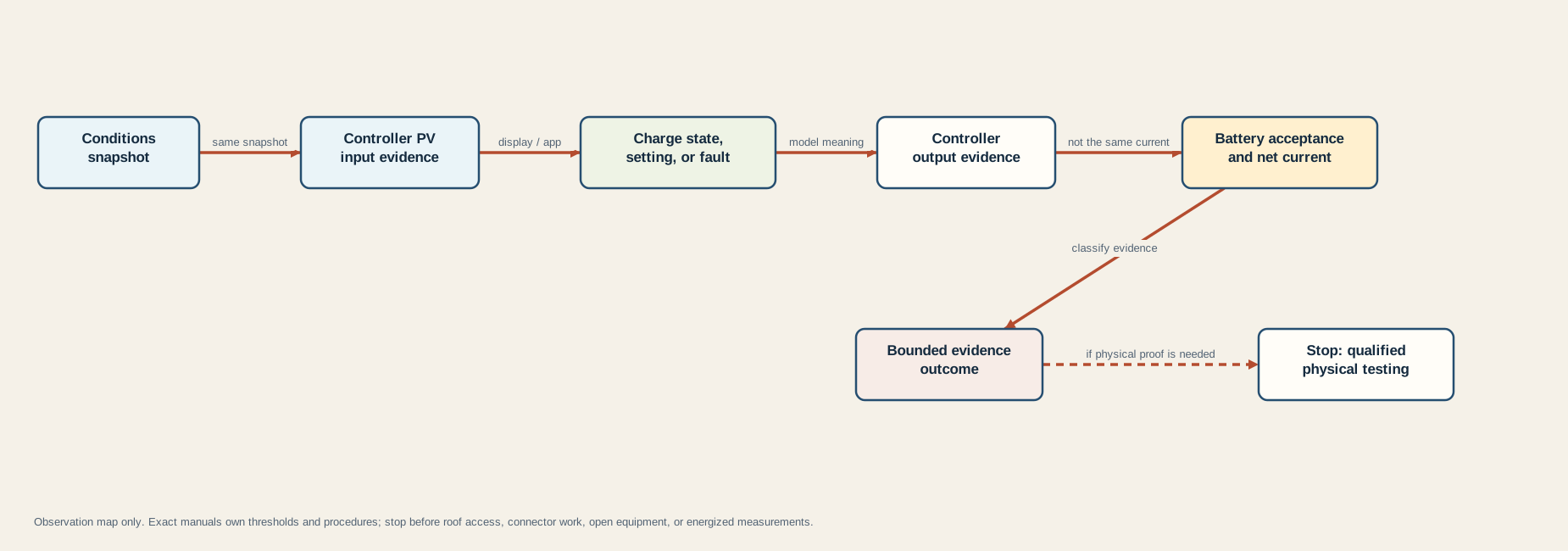
Follow the nodes in order:
- Conditions snapshot: Confirm that the reading belongs to a documented solar condition. Night and weak or rapidly variable sun are resource-limited states, not component diagnoses. Victron’s MPPT troubleshooting chapter lists night, cloud, shade, dirt, season, and orientation among reasons PV voltage may be too low.
- Controller PV input evidence: Use only values or status already available from the installed display, app, or monitoring portal at this stage. “PV present” means the controller reports an input; it does not validate roof connections, array polarity, conductor condition, or the accuracy of that sensor.
- Charge state, setting, or fault: Translate the exact state through the exact current manual. Charging may be disabled in settings, by a remote input, by an external controller, or by a BMS. A fault code is evidence of a documented state, not permission to use a generic reset sequence.
- Controller output evidence: Record reported output separately. Zero can be expected when a battery is full or charge is limited. Positive output establishes that the controller reports conversion at that moment; it does not prove how much reaches the bank.
- Battery acceptance and net current: Compare battery temperature, BMS state, charge settings, terminal-voltage trend, and whole-bank net current. Active loads can reduce or reverse net current even while the controller produces power.
The Morningstar TriStar manual independently lists settings, faults, open protection, polarity, insufficient array current, excessive load, voltage drop, and battery condition as separate causes of undercharging or no charging. That agreement supports the multi-node method. It does not make one manufacturer’s physical test procedure portable to another product.
The array topology may also create insufficient operating headroom or violate a controller input limit. Use the series-versus-parallel solar guide for design evidence and cold-Voc constraints. Do not rewire an existing array as a diagnostic shortcut.
Interpret the evidence patterns
Match the complete snapshot to the closest outcome. If two rows appear to match, keep both hypotheses and gather non-invasive history or product support evidence; do not choose the cheaper replacement part by guess.
| Fixture-tested outcome | Supporting pattern | Safe conclusion and next action category |
|---|---|---|
| Expected resource-limited | Night, weak/variable sun, or documented PV voltage below the exact controller’s operating requirement | No controller defect is established. Compare a later snapshot under suitable conditions and use the exact manual’s day/night behavior |
| Expected charge-limited | Battery is documented full, controller is in a normal limiting stage, or configured/external charge limits are active | Low or zero current may be normal. Verify that settings and battery profile match the exact manuals; do not force bulk charge merely to create current |
| Controller or battery inhibit | Controller reports disabled, external control, temperature limit, BMS stop, or a documented fault | Identify which device owns the inhibit and follow its current manual or support path. The controller may be obeying another device |
| PV-input evidence missing | Strong-sun snapshot but the controller reports absent/unknown PV input | The fault is not localized. Display logic, resource at the array, protection, wiring, and input stage remain candidates; physical proof crosses the service boundary |
| Loads exceed solar | Controller output is positive, whole-bank net current is negative, and meaningful loads are active | Solar is contributing but not covering current demand. Record loads and compare the controller-output and net-current boundaries before resizing anything |
| Charging present | Controller output is positive and a verified whole-bank monitor shows positive net current | Charging exists at that moment. If recovery is still poor, compare energy over time, battery capacity/acceptance, load history, and monitor accuracy |
| Qualified controller-path review | PV input is reported present, battery acceptance is allowed, controller output remains zero, and no normal limit is documented | Evidence is stronger but still does not prove a failed controller. Preserve the snapshot and use manufacturer support or qualified model-specific testing |
| Qualified service boundary | Controller cannot be observed safely, a fault calls for terminal checks, or proof requires roof, connector, open-panel, fuse, breaker, or energized measurement work | Stop owner-level diagnosis and hand the recorded evidence to qualified service |
| Insufficient evidence | Manual/model, PV input, charge state, battery acceptance, monitor boundary, or comparable conditions are unknown | Do not assign a failed component. Fill the observation record or retain unknown for service |
Three patterns deserve extra care.
PV voltage near battery voltage: Some controller types or states may show similar values, and specific manuals explain what that means for that product. It is not a universal proof of a shorted panel, PWM operation, a sleeping MPPT, or failed input. Use the exact controller’s operating description.
Controller says charging, battery state of charge does not rise: A shunt-based state-of-charge estimate can drift when settings or synchronization are wrong. The Victron SmartShunt manual explains that the monitor integrates current over time and requires appropriate charged-voltage, tail-current, time, capacity, and synchronization settings. Use the battery-monitor shunt audit to separate net current, bypass coverage, direction, settings, and synchronization before trusting the percentage trend.
Battery remains in discharge while solar power looks healthy: Compare units and boundaries. PV watts, controller output amps, and battery net amps are different quantities. Other charge sources may also raise battery voltage, while an inverter or large 12 V load may consume more power than the solar controller supplies. The correct question is not “is solar on?” but “what input, output, and net-bank state existed at the same time?”
Stop before observation becomes live PV work
Stop the owner-level path when the next missing fact requires any of the following:
- climbing onto the roof or working near an exposed array;
- separating, remating, or back-probing PV connectors;
- opening a controller, combiner, fuse holder, breaker enclosure, battery compartment, or distribution panel;
- bypassing the controller or connecting a panel directly to a battery;
- measuring controller terminals or open-circuit array voltage while illuminated;
- changing topology, polarity, protection, grounding, bonding, conductor size, or terminal torque;
- applying a reset, disconnect, or reconnection order copied from another model;
- waking, bypassing, or externally charging a protected lithium battery without its exact battery and charger procedure.
The cited Victron troubleshooting material explicitly warns that some solar controllers can accept dangerous PV voltages and reserves dangerous-voltage handling for qualified technicians. Go Power and Morningstar manuals include product-specific connection and test sequences; those sequences are evidence that procedure matters, not generic instructions for every RV.
Prepare a service handoff instead. Include controller and battery model labels, current manual links, the completed snapshot, screenshots with timestamps, exact fault text, recent history, whether shore or alternator charging works, known changes before the symptom, and which observation first became unknown. That record gives a technician a reproducible starting point without turning uncertainty into unsafe live work.
If the system also has unexplained 12 V outages, use the 12 V power troubleshooting map as a separate distribution task. If the issue involves neutral-to-ground behavior, chassis bonding, or AC equipment, stop and use the grounding and bonding guide only as a conceptual owner map, not as authorization to alter a bond.