
Deterministic candidate audit · fixture 1.0.0
RV DC-DC charger candidate checker
Audit one output-current setting using evidence you already have. Synthetic defaults demonstrate the fixture; they are not a charger recommendation or vehicle specification.
Overall candidate status
Needs evidence
The numeric demonstration is not a recommendation. Verify every source and physical-path gate.
- Estimated charger input
- —
- Candidate charger output
- —
- Battery current available after other chargers
- —
- Gross arithmetic over drive time
- —
- Arithmetic output needed for target
- —
Decision policy and fixture cases
Any failed gate rejects the candidate. If none fails but one is unknown, the result remains needs-data. Candidate-only requires all ten gates to pass and still does not approve installation or predict actual charge received.
- all-gates-pass: expected candidate-only
- alternator-headroom-fails: expected reject
- battery-current-fails: expected reject
- input-path-fails: expected reject
- output-path-fails: expected reject
- energy-target-fails: expected reject
- vehicle-evidence-missing: expected needs-data
- battery-evidence-missing: expected needs-data
- charger-evidence-rejects: expected reject
- path-evidence-missing: expected needs-data
- equal-current-boundaries-pass: expected candidate-only
- missing-numeric-input: expected needs-data
Use this checker to audit one DC-DC charger output setting that you already selected. It does not calculate a universal charger size from alternator nameplate amperage or battery amp-hours. The output setting must fit the verified vehicle headroom, battery charge ceiling, input path, output path, and drive-time goal at the same time.
Candidate-only is deliberately narrow. It means the entered arithmetic and evidence states agree under this fixture. It does not prove the values describe the RV, predict actual energy stored, select a charger, size a cable or fuse, approve engine-detection settings, or authorize installation.
Safety and limitations: Alternator, starter-battery, house-battery, and high-current 12V paths can deliver destructive fault current. Vehicle charging behavior can be computer-controlled and model-specific. Do not disconnect batteries, open equipment, probe an energized path, alter vehicle wiring, change protection, or install a charger using this page. Unknown alternator support, hot-idle capacity, terminals, isolation, conductor/protection design, grounding, charging profile, temperature control, or manufacturer instructions requires qualified vehicle-electrical review. Shore-power mains work remains outside this tool.
Audit one DC-DC charger candidate
The default values are a synthetic QA case: 40A charger output at 14.4V, 13.2V at the charger input, 95% documented efficiency, 50A verified alternator headroom, 50A battery charge ceiling, no other charging current, 50A limits on both current paths, two hours of driving, and an 800Wh gross target. They are not typical values and must not be copied to a vehicle.
Complete the evidence in this order:
- Record the exact vehicle, alternator or charging-system documentation, smart-alternator behavior, accessory state, operating RPM, and temperature conditions that support a continuous available headroom value.
- Record one candidate charger’s exact model, output-current setting, input/output voltage operating point, efficiency evidence, engine-detection behavior, temperature limits, and derating conditions.
- Record the battery bank’s exact maximum and recommended charge current, required profile, temperature limits, BMS behavior, and every other charger that may operate simultaneously.
- Audit the input and output conductor/protection paths separately. Enter only continuous limits already established by the relevant manuals and design basis.
- Use drive time and energy only as a planning screen. Do not treat the gross result as battery energy measured by a shunt.
The checker has ten gates. Five compare numbers: alternator headroom, battery available charge current, input-path current, output-path current, and gross energy target. Five preserve evidence: vehicle, battery, charger, input path, and output path. Any failure rejects the candidate. If none fails but any item is unknown, the result remains needs evidence. Only ten passes return candidate only.
This order prevents a common circular argument. A 40A charger is not suitable merely because a web page calls 40A reasonable for a certain battery size. The vehicle must support its input demand, the battery must accept its combined charging current, and both physical paths must independently support their side of the converter.
Start with documented load energy from the RV 12V load calculator and the separate battery runtime model. Daily watt-hours describe energy use; they do not prove alternator headroom or a safe DC current path.
Separate alternator input from charger output
The candidate’s output-current label is not automatically its alternator input current. For the limited arithmetic in this fixture:
estimated input A = output A × output V ÷ (input V × efficiency)
Efficiency is entered as a decimal in the formula. At the synthetic default values:
40 A × 14.4 V ÷ (13.2 V × 0.95) = 45.93 A estimated input
That result explains why copying “40A” to the input cable or alternator budget can be wrong. The charger is delivering 576W on its output side in the example. Supplying that output at a lower input voltage plus conversion loss requires more than 40A at the input.
This is a planning equation, not a current guarantee. The exact charger’s controls may cap input current, cap output current, reduce current at its voltage threshold, stop through engine-shutdown detection, taper with battery state, or derate with temperature. Victron’s current operation and configuration manual treats input-current and output-current limits as separate settings and shows how input-cable voltage drop participates in shutdown behavior. That product evidence demonstrates the distinction; it is not a transferable settings recipe for another charger.
The tool compares estimated input current with two different limits:
| Comparison | What its entered limit must represent | What it does not prove |
|---|---|---|
| Estimated input vs alternator headroom | Continuous vehicle-supported current still available under the documented condition | Alternator nameplate output at all RPM and temperatures |
| Estimated input vs input-path limit | Verified continuous limit for the exact conductor, protection, terminals, routing, and charger input requirements | Fuse size, cable size, or installation approval |
| Candidate output vs battery availability | Battery maximum charge current minus other simultaneous charge current | That the battery will accept full current for the whole drive |
| Candidate output vs output-path limit | Verified continuous limit for the exact charger-to-bank path | Product compatibility, protection coordination, or workmanship |
Equality passes a numerical comparator in the fixture. It does not create engineering margin or override a manual, tolerance, temperature condition, transient, applicable requirement, or qualified design decision.
Use the wire-size and voltage-drop candidate checker for each identified path and the fuse candidate audit for each separately proposed protective device. Neither tool supplies the missing vehicle or product evidence, and neither should be used to reverse-engineer a desired charger size.
Map the two current paths
The deterministic diagram uses the same fixture as the calculator:
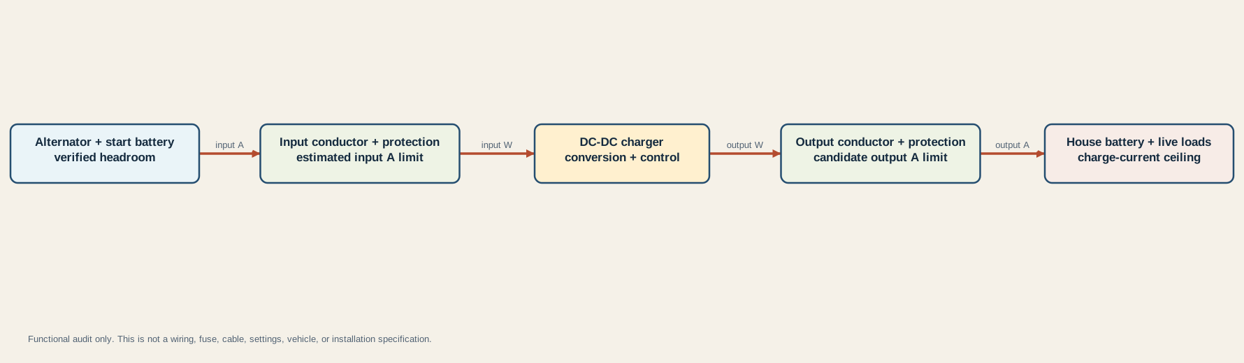
Read the five owners from left to right:
- Vehicle source: The alternator and starter-battery system own the available-headroom evidence. Headroom is what remains after the vehicle’s own continuous needs under the documented operating condition; it is not the alternator nameplate copied into the tool.
- Input path: Its conductor, protection, terminals, route, voltage drop, and every applicable charger input requirement own the estimated input current. A voltage-drop result alone is not an ampacity or protection result.
- DC-DC charger: Its exact manual owns conversion range, input and output current limits, charging modes, engine detection, low-voltage behavior, temperature limits, mounting, ventilation, and derating.
- Output path: Its conductor, protection, terminals, route, and equipment requirements own the candidate output current. It is not automatically identical to the input path.
- House bank: The battery documentation owns charge current, voltage profile, temperature, BMS limits, and permitted configuration. Live loads and other chargers change what reaches the cells.
Victron’s troubleshooting guidance identifies low idle output, other loads, alternator heating, charger heating, battery charge stage, and current-limit settings as possible reasons full rated output is not observed. The lesson is not to assume a particular idle percentage. It is to document the actual vehicle and operating condition instead of turning a nameplate into continuous available current.
The RV fuse-panel guide can help identify protection ownership, while the grounding and bonding guide keeps DC negative, chassis, equipment grounding, neutral, and source bonding terms separate. Neither article is an installation diagram for this high-current path.
Treat drive-time energy as a ceiling
The tool’s gross energy result is intentionally simple:
gross output Wh = candidate output A × entered output V × drive hours
The synthetic default produces 40 A × 14.4 V × 2 h = 1,152 Wh. The 800Wh target therefore passes the arithmetic gate. Rearranging the same values gives an arithmetic current floor of 800 Wh ÷ (14.4 V × 2 h) = 27.78 A.
Neither number predicts 1,152Wh entering the battery. The result is before:
- battery charge-stage taper or a battery already near full;
- battery temperature or BMS inhibition;
- house loads operating while the charger is active;
- charger current limiting, input undervoltage response, or thermal derating;
- alternator and vehicle voltage changes;
- conductor and connection voltage drop;
- conversion variation away from the entered operating point;
- a shorter real engine-running interval than the trip duration.
The Battle Born manual is one example of why battery data must be model-specific: it publishes charge-current, voltage, temperature, and BMS information for that exact product. Renogy’s DC-DC FAQ likewise checks charger compatibility against an exact battery maximum charge-current specification. Those values must not be copied to a different battery chemistry, model, bank arrangement, or temperature state.
Use a correctly installed battery-monitor shunt to distinguish charger output from net battery current during an actual observation. A shunt can show less charge current, or net discharge, while a charger is active if house loads consume the difference. The battery state-of-charge guide explains why a calculated percentage is also not a direct current measurement.
If the gross energy gate fails, the candidate does not meet the entered planning goal even before real-world reductions. If it passes, the tool only says the arithmetic ceiling is not already too small. It does not promise the trip will replace that energy.
Preserve evidence and stop before installation
Save a candidate record that another reviewer can reproduce:
| Evidence owner | Minimum record |
|---|---|
| Vehicle source | VIN/configuration, alternator or charging-system documentation, smart/regulated behavior, measured or manufacturer-supported continuous headroom, RPM, temperature, accessory state, test method, date, and reviewer |
| Charger | Exact model and revision, input/output range, selected output setting, efficiency evidence at the operating point, current limits, engine-detection method, voltage thresholds, thermal limits, mounting and ventilation requirements |
| Battery bank | Exact models, series/parallel configuration, maximum and recommended charge current, charging voltage profile, temperature range, BMS behavior, state of charge, and other active charge sources |
| Input path | Source and destination, total conductor path, exact cable and terminals, route, temperature and bundling, voltage drop, continuous-current basis, protective device and its coordination, manuals and applicable requirements |
| Output path | Charger and bank endpoints, exact cable and terminals, route, temperature and bundling, continuous-current basis, protective device and its coordination, manuals and applicable requirements |
| Energy goal | Source of required watt-hours, actual engine-running window, concurrent loads, battery acceptance assumption, expected derating, and measurement plan |
Stop when continuous alternator headroom is merely guessed from the nameplate, a percentage rule, a similar vehicle, or a forum comment. Also stop when the battery limit is inferred from amp-hour capacity alone; when another charger is omitted; when input and output paths are treated as one cable; or when the exact charger manual, vehicle support, protection, terminals, grounding, or engine-detection requirements are missing.
Do not interpret candidate-only as permission to raise an existing charger’s current setting. An existing system may have been limited for alternator temperature, input voltage, cable, protection, battery, BMS, vehicle integration, or other constraints that this page cannot see. Repeated shutdown, low input voltage, hot odor, discoloration, damaged insulation, unexpected battery isolation, or protection opening requires diagnosis rather than a larger setting.
The candidate audit is complete only when all ten gates pass with traceable evidence and an appropriate vehicle-electrical reviewer confirms the design context. Physical connection, source isolation, protection placement, conductor termination, torque, grounding, commissioning, and compliance remain outside this page.
Sources and limitations
The formulas and decision precedence are deterministic for the supplied inputs. They cannot determine whether the entered values are true for the physical RV. Victron supports the input/output-current, voltage-drop, operating-state, alternator-condition, and thermal concepts; Battle Born and Renogy illustrate battery-specific compatibility evidence. No source is converted into a universal vehicle rule or product recommendation.
Last verified: August 29, 2026. Recheck the exact vehicle, charger, battery, conductor, protection, and applicable documentation before relying on a saved audit.