
Deterministic candidate audit · fixture 1.0.0
RV solar sizing candidate checker
Test one proposed array against a declared energy case and exact manual limits. Defaults are synthetic QA data, not a product or installation recommendation.
Overall candidate status
Needs evidenceNumbers alone cannot approve the candidate.- Array needed — conservative case
- —
- Array needed — favorable case
- —
- Candidate array
- —
- Cold-corrected string Voc
- —
- Array Isc
- —
- Battery charge current available
- —
Decision policy and test coverage
Any failed gate rejects. If none fails but one is unknown, the result remains needs-data. Candidate-only requires ten passes and remains a planning audit, not approval.
- all-gates-pass: expected candidate-only
- energy-fails: expected reject
- cold-voc-fails: expected reject
- array-isc-fails: expected reject
- battery-current-fails: expected reject
- resource-evidence-missing: expected needs-data
- module-evidence-rejects: expected reject
- multiple-evidence-missing: expected needs-data
- missing-numeric-input: expected needs-data
Use this checker to audit one array and controller-output setting that you already selected. It gives two different answers: whether the candidate covers the declared conservative energy case, and whether its entered electrical and evidence constraints agree. Neither answer predicts harvest or selects a system.
Candidate-only is deliberately narrow. It means ten entered gates pass under this fixture. It does not prove that the entries describe the RV, that the roof receives the assumed sun, that the battery will absorb the expected energy, or that the equipment and installation comply with exact manuals and applicable requirements.
Safety and limitations: PV modules can produce voltage whenever illuminated, batteries can deliver destructive fault current, and an RV may also contain hazardous shore-power circuits. Do not disconnect live connectors, open equipment, short a module, probe exposed conductors, penetrate a roof, alter protection, or install equipment from this page. Exact module, controller, battery, conductor, protection, grounding, disconnect, attachment, sealing, and vehicle requirements need qualified review. This tool is not a wiring diagram.
Audit one solar candidate
The synthetic default demonstrates the fixture: an 800Wh daily target, 3.5 conservative and 5.5 favorable peak-sun hours, 70% and 80% delivered-efficiency assumptions, and two 200W modules in one two-module series string. The example module has 24.3V Voc, 10.8A Isc, and a −0.28%/°C Voc coefficient. The declared minimum cell temperature is −10°C. The controller inputs are 75V maximum PV Voc and 15A maximum PV Isc; its candidate output setting is 30A. The battery ceiling is 50A with 10A reserved for other chargers.
Those values are test data, not typical RV numbers. All six evidence selectors start at not verified, so the displayed arithmetic cannot appear approved by default.
Work through the candidate in this order:
- Build daily watt-hours from an actual inventory, not battery capacity or panel advertising. The 12V load calculator keeps each appliance’s watts and hours visible.
- Declare a location, season, parking pattern, shade case, orientation, and loss basis for both solar-resource assumptions.
- Copy watts, Voc, Isc, temperature coefficient, and reference conditions from the exact module datasheet.
- Copy maximum PV open-circuit voltage, maximum PV short-circuit current, output limits, temperature behavior, and array rules from the exact controller manual.
- Record the battery bank’s permitted charge profile, current, temperature, BMS behavior, and every simultaneous charger.
- Audit roof fit, attachment and sealing separately from PV and controller electrical paths.
The four numeric gates cover conservative energy, cold string Voc, array Isc, and battery charge-current availability. Six evidence gates cover resource, module, controller, battery, physical electrical paths, and roof/environment. Any failed gate rejects. If none fails but one is unknown, the result remains needs evidence. Only ten passes produce candidate only.
This is narrower than a “recommended solar kit” result. A 400W candidate can clear an energy equation and still fail cold voltage, input current, battery acceptance, roof fit, or missing manual evidence. Conversely, a controller-compatible array can remain too small for the declared conservative energy case.
Keep the energy range uncertain on purpose
The checker uses the same transparent equation twice:
required array W = daily energy Wh ÷ (peak-sun hours × delivered efficiency)
At the synthetic defaults, the conservative case is:
800 Wh ÷ (3.5 h × 0.70) = 326.53 W
The favorable case is:
800 Wh ÷ (5.5 h × 0.80) = 181.82 W
The two-module candidate is 200 W × 2 × 1 = 400 W, so it passes the conservative arithmetic gate. That result says only that 400W is not already below 326.53W under the declared model. It does not promise 800Wh per day.
The current Victron RV sizing guide also starts from energy use and peak-sun assumptions, while distinguishing controller voltage and current constraints. Its examples are useful illustrations, not universal loss percentages or location data for this tool.
NREL’s PVWatts manual documents why solar modeling depends on resource data, time period, array orientation, temperature, and loss assumptions. PVWatts models grid-connected PV and is not an RV design-approval engine; here it supports only the uncertainty lesson. A mobile RV changes orientation and location, roof hardware causes local shading, snow or dirt can cover modules, and parking choices often matter more than a fixed-roof annual average.
Treat “delivered efficiency” as a declared bucket for the modeled energy path, not a measured controller efficiency and not a constant law. Its evidence record should state what is included, such as temperature, mismatch, wiring, conversion, dirt, shade, and battery-charge effects, and avoid counting the same loss twice. Use location- and season-appropriate resource data when available. If the travel pattern is unknown, the resource gate stays unknown.
The battery runtime calculator answers a different question: how long an entered usable-energy budget supports an entered load. The battery-monitor shunt guide explains how actual net battery current differs from controller output while loads or other chargers are active. Neither converts an optimistic solar estimate into measured harvest.
Check electrical limits separately
Energy wattage does not establish electrical compatibility. The candidate audit performs three additional numeric comparisons.
First, it estimates cold series-string Voc using the module’s own coefficient:
cold string Voc = module Voc × [1 + coefficient × (minimum cell temperature − reference temperature)] × series count
The coefficient is entered as percent per °C and converted to a decimal. For the synthetic values, each module rises from 24.3V to about 26.68V at −10°C, so the two-module string is 53.36V. The tool requires cold string Voc to be below the entered controller maximum. Equality rejects deliberately because this audit creates no tolerance or design margin. The exact manual may impose an additional operational minimum, startup condition, safety factor, or other rule.
Victron’s current installation instructions explicitly require checking maximum PV open-circuit voltage and considering the module temperature coefficient. Morningstar’s ProStar MPPT manual likewise treats worst-case cold Voc as a hard array/controller constraint. Product examples establish the method, not transferable voltage limits.
Second, parallel strings add Isc in this simplified matched-module model:
array Isc = module Isc × parallel strings
The synthetic one-string candidate remains 10.8A and passes a 15A entered limit. Series modules do not multiply string current in this simplified calculation; parallel strings do. The exact Victron technical specification lists maximum PV open-circuit voltage, maximum PV short-circuit current, and maximum battery current as separate specifications. This tool therefore never substitutes controller output amperage for PV Isc.
Third, it compares the candidate controller output setting with battery charge current available after other chargers:
available battery charge A = bank maximum charge A − other simultaneous charge A
The synthetic result is 50A − 10A = 40A, so a 30A output setting passes the arithmetic gate. It does not prove compatibility. Battery chemistry, exact model, series/parallel bank configuration, state of charge, temperature, BMS state, charging voltage, controller profile, and other sources remain separate evidence.
Use the series-versus-parallel guide to understand topology tradeoffs without changing connections from a web example. Then audit each proposed conductor path with the wire and voltage-drop checker and each proposed protective device with the fuse candidate audit. Passing those tools still does not approve this system.
Map the evidence path
The deterministic diagram comes from the same fixture as the calculator:
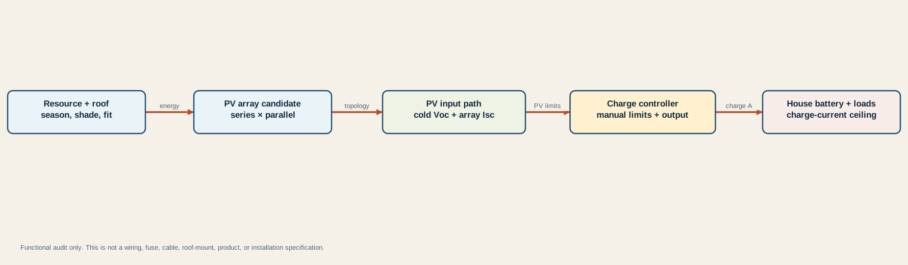
Read its five owners from left to right:
- Resource and roof: location, season, shade, orientation, usable area, attachment, sealing, clearance, wind, snow, branches, and service access.
- PV array candidate: exact module identity, matched-module assumptions, watts, Voc, Isc, coefficient, reference condition, and the declared series-by-parallel count.
- PV input path: cold string voltage, array current, conductors, connectors, protection, disconnects, route, temperature, and controller input requirements.
- Charge controller: exact PV voltage/current limits, operating window, output current, profile, temperature behavior, mounting, ventilation, grounding, and manufacturer rules.
- House battery and loads: bank configuration, charge-current ceiling, profile, temperature, BMS state, simultaneous sources, live loads, and observed net current.
The arrows are functional boundaries, not wires or connection instructions. The diagram intentionally omits terminals, polarity, fuse locations, disconnect placement, chassis connections, cable sizes, and roof penetrations. Those details cannot be generated safely from daily watt-hours.
If an existing system is underperforming, do not increase array size until the present path is understood. The solar-not-charging diagnostic separates resource, array, controller, battery, and output observations without encouraging live connector disassembly. More panel wattage does not repair a disabled controller, cold battery, open protection, poor connection, shading, or wrong profile.
Preserve evidence and stop before installation
Save enough data for another reviewer to reproduce the candidate:
| Evidence owner | Minimum record |
|---|---|
| Energy and resource | Load inventory date, daily Wh, operating season and location, peak-sun source, orientation, shade case, loss-bucket definition, weather margin, and reviewer |
| Modules and topology | Manufacturer, exact model/revision, quantity, series and parallel count, watts, Voc, Isc, Voc coefficient, reference condition, minimum cell-temperature basis, mismatch constraints |
| Controller | Exact model/manual revision, PV Voc and Isc limits, operating window, output limit/setting, battery profiles, temperature derating, grounding, mounting, ventilation, and permitted array rules |
| Battery bank | Exact models, configuration, maximum and recommended charge current, charge voltage, temperature range, BMS behavior, state, and every simultaneous charging source |
| Electrical paths | Endpoints, conductor and connector identity, total route, environment, ampacity basis, voltage drop, protection and disconnect coordination, terminal requirements, and applicable rules |
| Roof and environment | Measured usable area, obstruction/shade map, attachment method, structural approval, sealing, cable entry, clearance, wind/snow/branch exposure, service access, and inspection plan |
Stop when peak-sun hours came from an unrelated location or annual average; when the loss percentage is unexplained; when module data are copied from a similar panel; when minimum temperature refers only to ambient air without a stated design basis; or when a controller’s marketing amperage replaces exact PV input specifications.
Also stop when roof area is estimated from exterior dimensions, an attachment or penetration lacks vehicle/manufacturer support, connectors or modules are mixed without approval, another charger is omitted, battery limits are inferred from amp-hours alone, or conductor and protection choices are reverse-engineered from a desired array.
Candidate-only is not permission to buy or install. It is a compact statement that one documented candidate has not failed these ten specific gates. Before physical work, a qualified reviewer must reconcile exact manuals, applicable requirements, vehicle construction, grounding and bonding, protection, disconnects, roof integrity, and safe isolation. The grounding and bonding guide keeps DC negative and mains safety terms separate; the shore-power safety guide defines the stop boundary when hazardous AC conditions are involved.