
Deterministic candidate audit · fixture 1.0.0
RV 12V fuse candidate checker
Compare one proposed DC fuse with limits you already verified. The synthetic defaults demonstrate the fixture; they are not recommended ratings for an RV circuit.
Overall candidate status
Needs evidence
The numeric demonstration is not a recommendation. Complete every evidence gate with exact-source data.
- Lowest entered upper limit
- —
- Headroom to that limit
- —
- Voltage comparison
- —
- Interrupt comparison
- —
Decision policy and fixture cases
Any failed gate rejects the candidate. If none fails but one is unknown, the result remains needs-data. Candidate-only requires all ten gates to pass.
- all-gates-pass: expected candidate-only
- below-required-minimum: expected reject
- conductor-limit-fails: expected reject
- equipment-limit-fails: expected reject
- dc-voltage-rating-fails: expected reject
- interrupt-rating-fails: expected reject
- response-not-satisfied: expected reject
- holder-not-satisfied: expected reject
- placement-not-satisfied: expected reject
- manual-not-satisfied: expected reject
- critical-evidence-missing: expected needs-data
- equal-boundaries-pass: expected candidate-only
Use the checker above to audit one proposed fuse, not to ask for a universal RV fuse size. It compares the candidate with five numerical limits and five evidence gates. Any failure produces reject. If no gate fails but one is unknown, the result remains needs evidence. Only ten passes produce candidate only.
Candidate only is deliberately narrow. It means the values entered are mutually consistent under this fixture. It does not select a fuse family, prove a conductor safe, locate protection, approve a holder, verify workmanship, establish code compliance, or authorize installation.
Safety and limitations: A 12V battery system can deliver destructive fault current even when shore power is disconnected. This planning tool does not calculate prospective fault current, conductor protection, fuse response, or installation requirements. Do not remove, replace, bypass, upsize, relocate, or probe protection using this page. Heat, odor, discoloration, water, damaged insulation, a fuse that opens again, exposed conductors, uncertain isolation, or battery-terminal work requires qualified service and the exact equipment procedures. Shore-power mains work remains hazardous and outside this tool.
Check one RV 12V fuse candidate
The checker requires values that come from the actual circuit design, exact manuals, fuse datasheet, holder datasheet, and applicable requirements. It does not turn watts into amps, add a fixed margin, or round to the next commercial fuse size.
The default values are a synthetic QA case: a proposed 30A fuse, a 25A verified minimum, a 40A conductor-protection maximum, a 35A equipment maximum, a 15V maximum circuit voltage, a 32VDC fuse rating, 5,000A prospective fault current, and a 6,000A DC interrupt rating. They are not typical values and must not be copied to an RV.
Complete the inputs in this order:
- Identify the exact source, downstream conductor segment, equipment, holder, and next protection boundary.
- Enter the proposed fuse’s marked current rating and datasheet-backed DC voltage and interrupt ratings.
- Enter the verified minimum rating required for normal operation and permitted response. If no defensible minimum has been established, leave it blank.
- Enter the verified maximum overcurrent-device rating for the protected conductor under the chosen design basis.
- Enter the equipment manufacturer’s maximum permitted fuse or overcurrent protection.
- Enter the maximum possible circuit voltage, not merely the nominal battery label.
- Enter prospective fault current at the candidate location only when it has a defensible calculation, manufacturer value, or engineering basis.
- Mark each evidence gate verified only when its source, revision, conditions, and applicability have been recorded.
The RV wire-size and voltage-drop checker is a prerequisite because a fuse candidate cannot protect a conductor that has never been identified and evaluated. Daily amp-hours from the 12V load calculator are not a fuse input; energy per day and instantaneous protection are different tasks.
Trace the fuse current window
The current gate is a window, not one multiplier:
verified minimum fuse rating <= proposed fuse rating <= lowest verified upper limit
The upper limit displayed by the tool is the lower of the conductor-protection maximum and equipment maximum. If the conductor permits 40A but the equipment manual permits no more than 35A, the visible upper limit is 35A. If the equipment permits 50A but the conductor basis permits no more than 40A, the conductor governs.
The lower bound also needs a source. It may come from an exact product requirement, a documented normal-current and transient analysis, or another applicable design rule. The tool intentionally does not multiply the load by 125 percent. That multiplier appears in many search results, but its applicability depends on the governing context, load classification, equipment listing, protective-device behavior, and conductor rules. A generic multiplier cannot be presented as a universal RV answer.
Victron’s DC fuse guidance describes current rating, voltage rating, speed, and type as separate selection criteria and compares consumer and cable ratings in its system-design context. Littelfuse’s Fuseology selection guide adds ambient-temperature effects, transient behavior, holder features, rerating, and application verification. Those sources support a multi-constraint process, not a transferable one-line RV formula.
A fuse’s ampere marking is also not an instantaneous trip threshold. Eaton’s Fuseology handbook treats time-current curves as a core performance characteristic. A candidate that carries normal current may respond too slowly for the protected path, while a candidate chosen too close to a transient may open during normal startup. The exact fuse curve, temperature, load profile, and equipment requirement own that decision.
The tool treats equality as passing a numerical comparator. That is only arithmetic boundary behavior. An exact manual, time-current curve, tolerance, temperature condition, or applicable rule may still require more margin or a different device.
Verify voltage, fault, response, and holder gates
An ampere-only match can still fail. Read each gate independently:
| Gate | PASS means | FAIL means | NEEDS DATA means |
|---|---|---|---|
| Required minimum | Candidate is at least the verified minimum | Candidate is below the verified minimum | Candidate or minimum is absent |
| Conductor maximum | Candidate does not exceed the verified maximum OCPD for the protected conductor | Candidate exceeds that maximum | Conductor or protection basis is absent |
| Equipment maximum | Candidate does not exceed the exact equipment maximum | Candidate exceeds the equipment maximum | Exact equipment limit is absent |
| DC voltage rating | Fuse VDC rating is at least maximum possible circuit voltage | Fuse VDC rating is too low | Either voltage is absent or DC suitability is unclear |
| Interrupt rating | DC interrupt rating is at least prospective fault current at that location | Available fault current exceeds the rating | Either value lacks a defensible source |
| Numerical sources | Every numerical value is traceable to an applicable source | Sources conflict or do not support the inputs | Provenance is incomplete |
| Time-current response | Family, speed, curve, transient duty, and protection task were verified together | Response is unsuitable | Curve or operating profile is unresolved |
| Holder and environment | Exact holder, mounting, connections, temperature, and rerating were checked | An assembly constraint fails | Holder or environmental evidence is incomplete |
| Placement and coverage | Source-side location and protected conductor segment are documented | The candidate leaves the intended path unprotected | Physical path or next boundary is unclear |
| Manuals and requirements | Exact product documents and applicable requirements are satisfied | A required condition fails | Documents, revision, or applicability is unresolved |
The DC voltage gate must use the maximum voltage that can appear across the protective device, including charging conditions relevant to the system. Victron and Littelfuse both state that fuse voltage rating must equal or exceed circuit voltage and that AC and DC suitability are not interchangeable assumptions.
Interrupt rating answers a different question: can the device safely clear the fault current available where it is installed? Victron’s current Wiring Unlimited material specifically warns that lithium batteries can produce very high prospective short-circuit current and that a fuse with inadequate interrupt rating may fail catastrophically. Eaton likewise treats interrupting rating and system short-circuit current as core selection data. Battery capacity in amp-hours is not itself the prospective fault current value.
Do not choose a fuse family from a generic label such as “blade for small loads” or “Class T for every lithium system.” A family name does not replace the exact part’s DC voltage, interrupt, current, response, holder, temperature, mounting, and equipment compatibility data.
Map the protected conductor path
Protection has an owner and a boundary. The deterministic diagram uses the same fixture as the ten-gate tool:
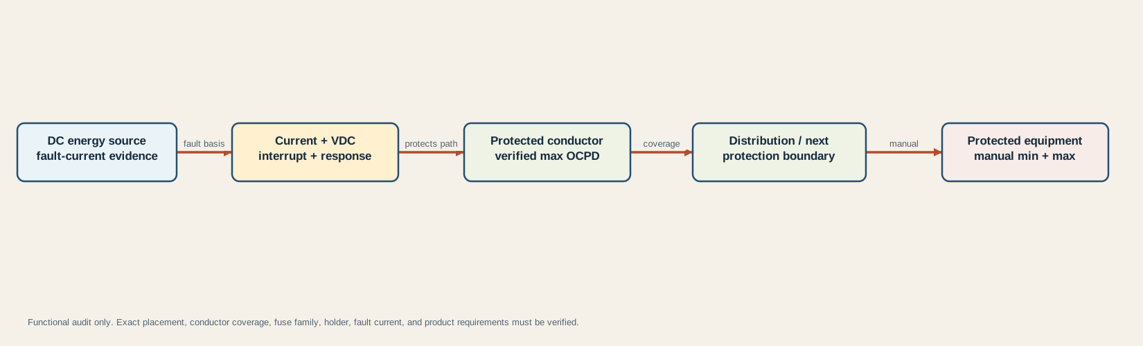
Read it from left to right:
- The energy source owns prospective fault-current evidence and every source that can energize the path.
- The candidate fuse owns current, VDC, interrupt, and time-current ratings plus its exact datasheet.
- The protected conductor owns the verified maximum overcurrent-device rating for its material, construction, insulation, route, temperature, bundling, and selected governing basis.
- The next protection boundary defines where this device’s coverage ends and another branch or protective device may begin.
- The protected equipment owns its minimum, maximum, fuse-family, transient, and installation requirements.
This is a functional model, not a wiring diagram or universal distance rule. Victron illustrates source-side battery protection, but exact placement and any permitted exception depend on the system design and applicable requirements. A fuse located somewhere in a distribution cabinet does not automatically protect an unprotected conductor segment between a battery and that cabinet.
Use the RV fuse-panel guide to distinguish branch, converter, upstream battery, and equipment-local protection. The panel guide identifies functional ownership; it does not assign a new rating. Likewise, do not use chassis or “ground” language to skip return-path analysis; the grounding and bonding guide keeps those functions distinct.
Preserve evidence and stop before installation
Save a candidate record that another reviewer can reproduce:
| Evidence record | Minimum contents |
|---|---|
| Circuit identity | Source, load, operating modes, protected conductor segment, next boundary, and every possible energizing source |
| Current window | Proposed rating, verified minimum, conductor maximum OCPD, equipment maximum, units, source IDs, revisions, and conditions |
| Voltage | Maximum circuit VDC, fuse VDC rating, charging or transient basis, and exact datasheet |
| Fault | Prospective fault current at the fuse, calculation or engineering method, source configuration, and fuse interrupt rating at DC conditions |
| Response | Exact fuse family and part, time-current curve, starting or transient profile, ambient temperature, and application test evidence |
| Assembly | Exact holder, mounting orientation, terminal and cable compatibility, connection requirements, enclosure, heat, and rerating |
| Placement | Distance and route evidence under the applicable requirement, protected segment, and upstream/downstream protection ownership |
| Approval boundary | Exact equipment manuals, battery documentation, applicable requirements, qualified reviewer, and unresolved assumptions |
Stop when any material value is unknown. In particular, do not estimate prospective fault current from battery amp-hours, assume the BMS replaces overcurrent protection, infer interrupt rating from fuse shape, treat a holder rating as the fuse rating, or copy a fuse from a similar-looking RV.
Do not use candidate-only status to replace a fuse in an existing faulted circuit. A fuse that opened performed an event that needs diagnosis. Replacing it without identifying the cause, or increasing its rating because it opens again, can expose the conductor or equipment to damage. Preserve the exact markings and system state, isolate sources according to the manuals, and use qualified service.
The audit is complete only when all ten gates pass with traceable evidence and an appropriate reviewer confirms the physical design. Even then, the result remains a candidate record, not a product recommendation, inspection, or compliance certificate.
Sources and limitations
The decision logic is deterministic for the supplied inputs. It cannot establish whether those inputs describe the real installation. Victron is used for DC system and lithium fault-current context; Littelfuse and Eaton are used for manufacturer-level fuse selection, voltage, response, holder, and interrupt concepts. Their guidance is not copied into a universal RV table.
Last verified: August 29, 2026. Recheck fuse, holder, battery, conductor, equipment, and applicable documentation before relying on a saved audit.