RV grounding is not one wire or one rule. Five different ideas are routinely compressed into the word ground: the 12V negative return, the metal chassis, the AC equipment grounding conductor, the AC neutral, and contact with earth. A sixth idea, the neutral-to-ground bond, connects two of those paths at a defined location. Mixing them can turn a useful safety concept into dangerous advice.
The reliable question is not “Is this RV grounded?” It is: Which AC source is active, where does that exact system document the neutral-to-ground bond, how is neutral switched, and can fault current return through a continuous equipment-ground path to the active source? If any part is unknown or conflicts with another manual, the mode is not verified.
Safety and limitations: This is a documentation and system-concept guide, not a wiring or test procedure. RV AC equipment can expose lethal voltage, and an incorrect bond can energize chassis metal, place normal neutral current on equipment-ground paths, defeat intended switching, or mask another fault. Owner work stops at current manuals, safely visible labels and indicators, and external preconnection checks explicitly permitted by the RV and equipment manufacturers. Do not open a panel, deadfront, inverter, transfer switch, generator, pedestal, or bonding device; do not add or remove a bonding plug, jumper, ground lift, relay, or conductor; and do not perform continuity or resistance tests on energized or connected equipment. Reject an unsafe source and use qualified RV electrical service for physical verification or changes.
Separate DC negative, chassis, neutral, equipment ground, and earth
Start by giving every path one name and one job. A conductor can be intentionally connected to chassis at a designed point without becoming interchangeable with every other conductor connected there.
| Term | Normal role | Carries current in normal operation? | What it does not prove |
|---|---|---|---|
| 12V DC negative | Return path for house-battery and converter-fed DC circuits | Yes, for operating DC loads | It does not identify the AC neutral or the AC source bond |
| Vehicle/RV chassis | Structural metal that may be used as part of the designed DC return and bonds exposed conductive equipment | It may carry designed DC return current; it should not become an unintended AC normal-current path | A DC-negative chassis connection does not prove AC equipment-ground continuity |
| AC neutral (grounded conductor) | Normal return path from 120V loads to the active AC source | Yes | Neutral is not the equipment grounding conductor and is not an owner-added safety jumper |
| AC equipment grounding conductor (EGC) | Bonds exposed conductive parts and provides a low-impedance fault-return path toward the active source | Not as a normal load-current path; it carries current during a fault | A receptacle working or a GFCI resetting does not prove this entire path is correct |
| Earth/soil | Reference to earth through the source or premises grounding arrangement as designed | Not the substitute return conductor for clearing a line-to-case fault in the RV | Tires, stabilizers, wet ground, or a ground rod do not replace the EGC path |
| Neutral-to-ground bond | Defined connection that establishes the source reference and completes the intended fault-current loop | It should not make downstream EGC paths carry ordinary neutral current | More bonds are not more safety; duplicate and missing bonds are different faults |
OSHA’s grounding overview distinguishes system/service grounding from equipment grounding. Its equipment-ground principle is the key here: the path must be permanent, continuous, and capable of carrying enough fault current for protection to operate. Victron’s ground, earth, and electrical-safety chapter similarly separates earth, chassis, and circuit ground and explains why the protective path and source bond must be considered as a system.
Imagine an energized AC conductor contacting a metal appliance case. The protective outcome depends on the case being bonded through the equipment-ground path back toward the active source bond so fault current can cause protective action. Soil beneath the tires is not that engineered metallic return path. A person touching the case must never become the bridge.
The neutral is different. It normally carries load current. In the source arrangement documented for RV shore operation, neutral and equipment ground are connected at the proper upstream source point but remain separated in the RV downstream. Joining them again downstream can place ordinary neutral current on equipment-ground and chassis paths. That is why a visually simple jumper can change the safety behavior of an entire system.
GFCI protection is another distinct layer. A GFCI looks for an imbalance between conductors carrying operating current; it does not certify that source bonding, equipment-ground continuity, polarity, overcurrent protection, or transfer switching is correct. Conversely, an equipment-ground path does not replace GFCI protection where required. The RV electrical system overview separates the 12V and 120V systems, while the power-center guide explains why owners should not infer internal bus relationships from the word “panel.”
Use the role table as a vocabulary gate. If a manual, forum answer, tester label, or service note says only “ground,” rewrite it in your record as the exact claimed path. If you cannot tell whether it means DC negative, chassis, EGC, earth, or a neutral bond, the evidence is incomplete.
Identify the active source and bond owner
A neutral-to-ground bond belongs to a source mode and topology, not to the RV as a vague permanent property. Shore power, a generator, a standalone inverter, and an inverter-charger can each change which device is the active source and how neutral is transferred. The same outlets may be energized in multiple modes while the required bond owner changes behind them.
Build one dated evidence record before classifying any mode:
| Evidence field | Record exactly | Why it controls the result |
|---|---|---|
| Active source | Shore pedestal, named generator, named inverter, or named inverter-charger in the observed mode | Only the active source can be evaluated; an installed but inactive source does not own the current mode |
| Source identity | Manufacturer, complete model/suffix, manual title or revision, and access date | Bonding and relay behavior can differ inside one product family |
| RV identity | Manufacturer, model, model year, floor plan, and documented electrical changes | Factory transfer and distribution designs vary; prior modifications can invalidate the factory drawing |
| Transfer equipment | Exact automatic/manual transfer device and every source it selects | The device can switch hot only, hot and neutral, or coordinate another relay; category is not enough |
| Neutral behavior | Whether neutral is switched in this exact mode, from the current manufacturer diagram | Bond ownership cannot be inferred without knowing what remains connected |
| Source bond | Exact manual statement or diagram showing where neutral and protective ground are related | A tester symptom or generic product label is not a substitute for source documentation |
| Downstream separation | RV distribution evidence that neutral and equipment ground remain separated where required | An unintended downstream connection can create parallel normal-current paths |
| Chassis/EGC path | Qualified verification and relevant RV/equipment documentation | The path must be continuous and suitable for fault current, not merely visually present |
| Recheck trigger | Generator, inverter, transfer, firmware, shore equipment, wiring, or manual change | The classification is not portable to a changed configuration |
Samlex’s RV and marine neutral-to-ground switching note shows why mode matters. In its documented shore/pass-through example, the upstream shore source supplies the bond and the RV-side neutral is not locally bonded. In inverter mode, an internal relay establishes the source relationship described for that exact inverter arrangement. Hot, neutral, transfer, and bonding behavior are coordinated; extracting one relay from the diagram would be misleading.
Victron documents a comparable principle but not one universal implementation. Its inverter-charger material describes a ground relay that changes state with input and inverter operation, while standalone inverter grounding behavior varies by product and rating. Morningstar’s SureSine manual documents model- and transfer-specific internal/external bonding choices, including different transfer-pole implications. Those examples prove variation, not that an unseen RV uses any one topology.
This matters most with portable generators. “Portable” does not establish bonded or floating neutral, and the receptacle face does not expose internal bonding. The generator manual, exact transfer arrangement, and downstream system must agree. If the manual is missing, a label is ambiguous, or the transfer/neutral state is undocumented, record MISSING EVIDENCE. Do not fill the gap with a generic generator rule.
The record has three outcomes:
- DOCUMENTED MODE: exact source, transfer behavior, bond owner, downstream separation, chassis/EGC path, and current manuals agree for the declared operating mode.
- MISSING EVIDENCE: a decisive model, revision, relay state, neutral behavior, bond statement, or path verification is absent. Unknown is not permission to modify.
- CONFLICT: STOP + SERVICE: two authoritative records disagree, a field condition contradicts the documented design, or evidence shows a duplicate/missing bond or unsafe supply state.
Use the shore-power safety check to qualify a campground source before connection. Use the converter-versus-inverter guide when an equipment name is being used for the wrong function. Neither page substitutes for the exact bond-owner record here.
Read shore, generator, and inverter modes
The map below is an evidence flow, not a wiring diagram. It intentionally omits terminals, colors, conductor sizes, and connection instructions.
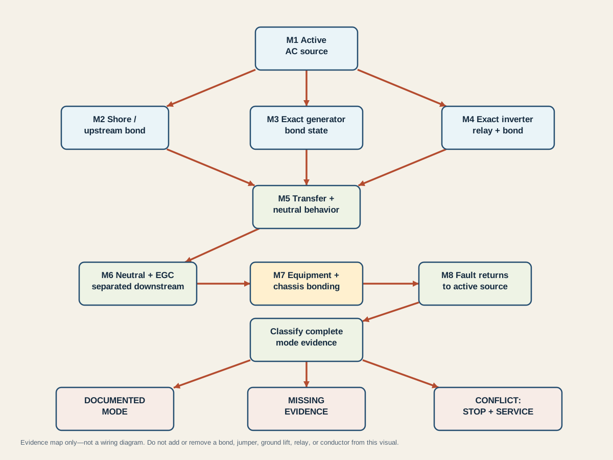
Read M1 first: identify the source actually energizing the RV. Then use only the applicable evidence branch: M2 for accepted shore power, M3 for the exact generator, or M4 for the exact inverter/inverter-charger. M5 requires the actual transfer and neutral behavior. M6 and M7 preserve downstream separation and the equipment/chassis protective path. M8 asks whether a fault has a documented path back toward the active source.
| Source mode | Bond-owner evidence needed | Transfer/neutral evidence needed | What remains unknown without exact documents |
|---|---|---|---|
| Shore power | Accepted supply arrangement documents the upstream source bond | RV inlet, cord, transfer equipment, and distribution preserve the required neutral/EGC relationship | Pedestal acceptance, cord continuity, prior modifications, and internal bus condition cannot be inferred from working appliances |
| Generator | Exact generator manual identifies its neutral/bond state for the configured use | Exact RV transfer documentation identifies whether neutral is switched and what remains connected | Bonded versus floating cannot be guessed from portability, wattage, plug style, or a generic tester indication |
| Standalone inverter | Exact inverter manual identifies chassis, output-neutral, and internal/external bond requirements | Exact transfer or dedicated-circuit arrangement defines isolation from other sources | Similar case design, rating class, or another model’s diagram does not establish this unit’s behavior |
| Inverter-charger/pass-through | Exact manual identifies the source-dependent bond/ground relay behavior | Exact mode and transfer logic identify whether external AC is accepted or the inverter is forming the source | “Inverter on” does not prove inverter mode; pass-through may leave the upstream source in control |
For accepted shore power, the documented conceptual result is an upstream source bond, RV-side neutral/EGC separation, bonded equipment/chassis, and a continuous equipment-ground path back through the cord and supply. It is not permission to inspect a pedestal or RV panel internally. The 2026 Jayco owner manual tells owners not to use campsite power with open-ground or reverse-polarity indications; that owner-facing rejection boundary is safer than attempting a field repair.
For generator mode, there is no safe universal completion to the diagram. A generator with one documented bond and a transfer arrangement designed for it may be a valid source. A different generator or neutral-transfer design can require different behavior. Adding a bonding plug because a portable tester reports open ground can be wrong if another bond remains connected; omitting a required source relationship can also be wrong. Only the exact evidence chain can distinguish them.
For inverter operation, first distinguish inverting from pass-through. An inverter-charger may be powered on while accepted shore input still supplies the loads. Manufacturer diagrams often change a ground relay only when the inverter becomes the source. A standalone inverter feeding dedicated receptacles may have another documented arrangement. Never transfer Samlex, Victron, or Morningstar internal behavior to a different brand or model.
The final result follows the weakest evidence:
| Evidence state | Diagram outcome | Meaning |
|---|---|---|
| All applicable M1 through M8 facts agree | DOCUMENTED MODE | The record describes one exact source mode; it is not installation approval or a universal rule |
| A decisive model, manual, transfer, bond, or path fact is absent | MISSING EVIDENCE | Keep the mode unclassified and obtain manufacturer or qualified-service evidence |
| The source/bond record conflicts with transfer behavior, downstream separation, or field evidence | CONFLICT: STOP + SERVICE | Do not energize or improvise a correction; preserve the evidence for qualified diagnosis |
If outlets fail only in one source mode, the RV outlets diagnostic owns the source-zone-protection symptom path. It deliberately does not authorize changing a bond. Keep the symptom record and bond-owner record separate so a tripped GFCI, transfer issue, missing source, and grounding conflict are not collapsed into one guess.
Interpret unsafe or unresolved states without adding a bond
An unresolved state calls for a narrower next action, not a more aggressive test. Start with what can be observed without opening equipment, touching exposed parts, or energizing a suspect source.
| Observation or evidence state | Bounded action | Why no field workaround is justified |
|---|---|---|
| Pedestal monitor or manufacturer-approved preconnection device reports open ground or reverse polarity | Do not connect; use another accepted source or campground/electrician support | The RV cannot repair a defective upstream supply, and an adapter cannot validate it |
| Tingling, shock, or any indication that chassis/body metal may be energized | Stop contact, disconnect only by a safe upstream method if possible, keep others away, and call emergency/qualified help as conditions require | A person must not become the fault-current path; do not touch RV and earth-referenced metal together |
| Generator bond state is absent or ambiguous in its exact manual | Keep that source unclassified and contact the manufacturer or qualified RV electrical service | A generic bonding plug may create a duplicate bond or conflict with neutral switching |
| Inverter manual and transfer documentation imply different neutral/bond behavior | Keep the affected mode out of service and preserve both documents for diagnosis | Opening the inverter or transfer device does not resolve which design is correct and exposes hazardous energy |
| GFCI trips, will not reset, or behaves differently by source | Use the mode-specific outlet diagnostic within its owner boundary; escalate unresolved results | A GFCI response identifies an imbalance/protection state, not the location or correctness of the source bond |
| Outlets and appliances appear normal | Continue only within an already documented source mode; retain the evidence record | Normal operation does not prove polarity, EGC continuity, chassis safety, or absence of parallel neutral current |
| Unapproved adapter, ground lift, homemade jumper, or unexplained bonding device is present | Keep it out of use and have the complete topology identified by qualified service | Removing or using it without system evidence can change the active bond state |
| Manuals are current but a prior modification is visible or documented | Treat the factory topology as unverified and route it to qualified service | Factory diagrams no longer establish the as-built conductor and relay relationships |
Do not use an ohmmeter or continuity tester on connected or energized equipment. Capacitors, parallel paths, surge devices, transfer relays, inverter electronics, and other connected sources can make a reading hazardous or ambiguous. Proper de-energization, isolation, absence-of-voltage verification, conductor identification, and interpretation belong to qualified work under the exact service information.
Do not treat a disclaimer, rubber tires, stabilizer position, dry ground, surge protector, GFCI, EMS, or working breaker as a substitute for evidence. These elements have different jobs. The fuse-panel and power-center guide further separates branch protection, distribution, conversion, and enclosure boundaries.
Save the result as a maintained record: exact RV and source models, manual titles/revisions, access date, active mode, transfer and neutral behavior, documented bond owner, downstream separation evidence, chassis/EGC verification owner, unresolved conflicts, and the final outcome. Reopen it after a source, inverter, generator, transfer switch, power center, cord, inlet, firmware, wiring, or manual change.
The safest useful conclusion is often not “add a bond” or “remove a bond.” It is DOCUMENTED MODE, MISSING EVIDENCE, or CONFLICT: STOP + SERVICE. That vocabulary preserves what is known, blocks a universal modification from crossing between unlike systems, and gives qualified service an auditable starting point.