
Deterministic candidate audit · fixture 1.0.0
RV DC wire-size and voltage-drop checker
Evaluate one proposed copper conductor. A good voltage-drop result is only one gate; missing ampacity, cable, terminal, or equipment evidence remains missing.
AWG resistance presets are converted from Victron's published Ω/m reference table. Selecting a preset does not verify the cable in your hand. Edit the value when exact cable data differs.
Overall candidate status
Needs evidence
Calculating the cable-only voltage drop…
- Total conductor path
- —
- Cable-only drop
- —
- Estimated load voltage
- —
- Cable loss at design current
- —
Equation and verified fixture cases
drop V = current A × resistance Ω/1,000 ft × total path ft ÷ 1,000
drop % = drop V ÷ system voltage V × 100
- drop-fails: expected reject
- all-gates-pass: expected candidate-only
- ampacity-fails: expected reject
- terminal-fails: expected reject
- evidence-missing: expected needs-data
- total-path-equivalence: expected candidate-only
Use the checker above to audit one proposed copper conductor for one RV DC circuit. It calculates cable-only voltage drop, then keeps that result separate from four facts a formula cannot invent: resistance for the exact cable, adjusted allowable ampacity, terminal fit, and the exact equipment manual.
The safest useful result is therefore not “recommended gauge.” It is one of three bounded states: reject, needs evidence, or candidate only. Candidate only means every entered gate passes; it is still not a fuse recommendation, code determination, workmanship inspection, or permission to energize the circuit.
Safety and limitations: This high-risk planning tool does not design a complete circuit or approve installation. It cannot verify cable construction, insulation, temperature, bundling, conduit, terminals, crimp quality, routing, mechanical protection, fault current, overcurrent protection, chassis-return suitability, equipment limits, or applicable requirements. De-energize safely and use qualified help for conductor selection, modifications, damaged wiring, heat, discoloration, odor, arcing, exposed conductors, uncertain protection, or any shore-power mains work.
Check one RV DC conductor candidate
Start with a conductor you are considering, not with a desired answer. The five calculated and documented gates are intentionally independent:
- Voltage drop: Does the cable-only estimate meet the drop target you entered?
- Resistance basis: Did you verify resistance for the exact cable and relevant conditions rather than accepting a reference preset as proof?
- Adjusted ampacity: Is the verified allowable current after applicable installation adjustments at least the design current?
- Terminal fit: Does the cable, insulation, lug, bend radius, and finished termination fit every endpoint?
- Equipment manual: Does the exact product’s required cable, length, terminal, and protection guidance remain satisfied?
The checker applies a conservative decision order. Any failed gate produces reject. If no gate fails but one is unknown, the result is needs evidence. Only five passes produce candidate only. This prevents a low voltage-drop percentage from overruling a thermal or mechanical failure.
Enter design current, not daily average current from an energy worksheet. A 12V load calculator answers how much energy loads may consume over time; this tool needs the current the conductor must carry in the relevant operating state. Starting surge, charger maximum output, inverter DC demand, and fault behavior may require separate treatment under the exact manuals.
The AWG menu is a convenience for testing the equation. Its resistance values are converted deterministically from the AWG table in Victron’s Wiring Unlimited DC wiring chapter:
Ω per 1,000 ft = Ω per meter × 304.8
Selecting “6 AWG,” for example, prefills 0.00130 Ω/m × 304.8 = 0.39624 Ω/1,000 ft. It does not prove that every cable sold as 6 AWG has that resistance, material, strand construction, temperature behavior, or insulation rating. The checker deliberately clears the resistance-verification gate when you switch presets.
Distinguish one-way route from total conductor path
Voltage drop follows the complete current path. Blue Sea Systems’ DC wire-selection guidance defines circuit length as the round trip from source to load and back. Victron likewise states that its cable calculation covers both cables and that its tables use positive-plus-negative total cable length.
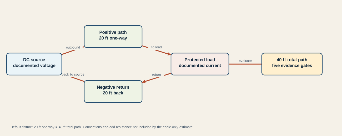
Choose the input mode that matches what you measured:
- One-way route: enter source-to-load distance and let the checker double it. This is correct only when the return route is the same length.
- Total conductor path: add the actual positive and return conductor lengths yourself, then enter that total. The checker does not double it.
The default fixture makes the factor-of-two visible. At 15A, 12V, and 0.39624 Ω/1,000 ft, a 20-foot one-way route becomes 40 feet total:
drop = 15 A × 0.39624 Ω/1,000 ft × 40 ft ÷ 1,000 = 0.237744 V
drop % = 0.237744 V ÷ 12 V × 100 = 1.9812%
Entering 40 feet in total-path mode produces exactly the same result. Entering 20 feet as total path would omit half of this fixture’s cable. Entering 40 feet as one-way would double it twice.
Do not automatically substitute geometric distance or a chassis dimension for conductor length. The electrical return may follow a different route, and deciding whether a chassis path is suitable is a topology, bonding, connection, and applicable-requirements question, not a checkbox in this calculator. See the conceptual RV grounding and bonding guide before treating “ground” and DC negative as interchangeable terms.
Read the five gates separately
The equation is straightforward; the evidence is the hard part. The checker reports both so that uncertainty remains visible.
| Gate | PASS means | FAIL means | NEEDS DATA means |
|---|---|---|---|
| Voltage drop | Cable-only drop is at or below your stated target | Cable-only drop exceeds your target | Invalid numerical inputs block the entire result |
| Resistance basis | Exact cable resistance and relevant basis were checked | Not used; an unsupported resistance remains unknown rather than false | The AWG reference preset has not been verified against the exact cable |
| Adjusted ampacity | Verified adjusted allowable ampacity is at least design current | The verified value is below design current | No installation-appropriate value was supplied |
| Terminal fit | Every endpoint and bend constraint was checked | The finished cable or termination does not fit | Terminal, lug, insulation, or bend evidence is incomplete |
| Equipment manual | Exact product requirements are satisfied | A product requirement is not satisfied | The exact manual was not checked or is unclear |
Voltage drop and ampacity are not two names for the same constraint. Blue Sea notes that its chart assumes a particular insulation rating and that a lower rating reduces current-carrying capacity. Victron discusses heat dissipation, cable construction, routing, and the product manual. Those sources support the need to check both constraints; they do not turn a marine table or one manufacturer’s example into a universal RV ampacity table.
The voltage-drop target is also an input, not a universal permission slip. Blue Sea’s 3% and 10% categories come from a marine design context. Victron advises aiming below 2.5% in its system-design context. The connected equipment may impose a different maximum or cable-length limit. Set the target from the exact product instructions and applicable design requirements, record its source, and use the stricter applicable constraint. The tool treats equality as meeting the entered target.
Cable loss is shown as current × cable drop. It helps audit internal consistency; it is not a thermal model. The displayed load voltage subtracts cable-only drop from the entered source voltage and does not predict battery sag, converter regulation, connector drop, or transient behavior.
Verify the cable, route, terminals, and manual
Before marking any evidence gate verified, preserve a worksheet that another reviewer can reproduce:
| Record | What to preserve | Why it matters |
|---|---|---|
| Circuit owner | Exact source, load, operating mode, and design-current source | Prevents a daily average or normal current from replacing a required maximum or surge case |
| Route | Positive length, return length, measurement method, and route conditions | Makes round-trip length and heat exposure auditable |
| Cable identity | Manufacturer, part number, conductor material, construction, insulation rating, and markings | AWG alone does not identify every electrical and mechanical property |
| Resistance | Published value, unit, temperature basis if supplied, and accessed date | The cable-only formula is only as defensible as its resistance input |
| Ampacity | Source table or engineering basis plus every relevant adjustment | A bare nominal value can ignore temperature, bundling, conduit, insulation, and application scope |
| Terminations | Stud or connector requirements, approved lug, tooling, bend space, strain relief, and enclosure clearance | A conductor that works numerically may be impossible to terminate correctly |
| Equipment manual | Required size, maximum length, fuse/protection instructions, torque, and other product limits | Product requirements can be stricter than the planning calculation |
| Protection | Separate conductor-protection and equipment-protection decision | Voltage drop never selects a fuse by itself |
Victron’s theory chapter identifies fuses, shunts, switches, terminals, crimps, connection quality, and corrosion as additional resistance sources. This checker intentionally estimates cable only because connection resistance cannot be guessed honestly. If measured end-to-end performance differs from the cable estimate, do not “correct” the tool by assuming an arbitrary connection allowance; investigate with an appropriate, safe test plan and qualified help.
The same boundary applies to parallel conductors. Dividing current perfectly between two cables is an assumption about equal path resistance, terminations, protection, and applicable rules. This page does not model or approve parallel cable runs.
Stop before calculation becomes installation approval
Stop at candidate only. The label means the values you supplied are mutually consistent under this fixture; it does not certify the physical circuit.
Do not use this result alone to:
- choose or relocate a fuse or breaker;
- decide where conductor protection begins or ends;
- approve a chassis return, parallel conductors, or battery-bank topology;
- accept cable with unknown material, undersized core, damaged insulation, or unreadable markings;
- force an oversized conductor into a terminal or modify equipment to make it fit;
- copy a marine, automotive, household, or manufacturer table outside its stated scope;
- probe, disconnect, or modify an energized DC system; or
- perform any shore-power mains work.
The RV 12V fuse candidate checker owns the next protection-planning step. It compares one proposed device with verified conductor and equipment limits, DC voltage, prospective fault current, response, holder, placement, and manual evidence. It still does not replace exact equipment instructions or qualified design review. The RV fuse-panel guide explains functional ownership but does not size protection for a new circuit.
Treat the audit as complete only when every input is traceable, both length modes reproduce any worked comparison, all five gates pass, product-specific requirements are preserved, and a competent reviewer can explain what the calculator did not check.
Sources and limitations
The formulas and fixture cases are deterministic. The installation evidence is not: it depends on exact products, actual routing, environment, workmanship, governing requirements, and inspection. Blue Sea Systems is a marine source and Victron is a manufacturer/system-design source; each is used within its stated context to verify principles and expose limitations, not to claim universal RV compliance.
Last verified: August 29, 2026. Recheck exact cable and equipment documentation before relying on a saved candidate audit.