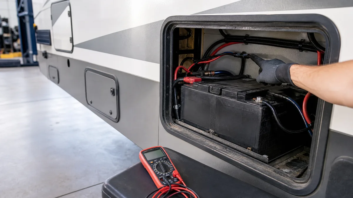
An RV battery that appears not to charge on shore power can have a problem at several different points: the incoming AC source, the converter’s DC output, a battery-path fuse or disconnect, a loose return connection, or the battery itself. A single voltage reading cannot identify which point failed.
This guide is a bounded diagnostic sequence for an owner who can read the equipment labels, observe breakers and disconnects, and use a meter only at accessible points allowed by the installed manual. It is not permission to open a 120V panel, remove a converter, disconnect live battery cables, or replace a fuse with a different rating.
Stop and get qualified help: stop for heat, smoke, burning odor, melted insulation, swelling or leaking batteries, water intrusion, a tripped breaker that immediately trips again, damaged shore-power equipment, exposed conductors, or any test that requires opening an energized AC enclosure. A disclaimer does not make hazardous mains-voltage work safe.
Set the safe diagnostic boundary
First write down the symptom in a way another person could reproduce. For example: “The RV is plugged into an accepted shore source, interior 12V lights work, but the battery monitor does not show expected charging after the normal load is removed.” That is more useful than “the converter is bad.”
Record these facts before interpreting a number:
| Record | Why it changes the interpretation |
|---|---|
| Exact converter or power-center model and manual revision | Output targets, fuse locations, and test procedures are model-specific. |
| Battery chemistry, nominal voltage, capacity, and manufacturer charging limits | Lead-acid, AGM, and lithium systems can use different charge profiles and protection behavior. |
| Shore or generator source and how it is accepted by the RV | The converter cannot produce DC output without its required AC input. |
| Battery-disconnect position and visible DC protection | A disconnect, inline fuse, auto-reset breaker, or reverse-polarity fuse can interrupt the battery path. |
| Loads running during each reading | Converter current may be supporting loads before any remaining current reaches the battery. |
| Measurement node and time since the source or load changed | A battery-terminal reading is not the same test as a converter-output reading. |
Progressive Dynamics and WFCO both place source, converter, fuse, wiring, and battery checks in a sequence rather than treating replacement as the first step. Their procedures differ by model, so use their instructions as examples of the evidence chain, not as a universal wiring layout. The RV electrical system overview explains the separate AC source, converter, DC distribution, and battery roles.
If the equipment roles are still unclear, review the RV converter versus inverter comparison before interpreting a charging symptom. A converter, inverter, and inverter/charger do not answer the same diagnostic question.
Do not infer charging from a brighter light, a running fan, or a powered control panel. Those observations show that some 12V load is receiving energy, not that the battery is accepting current.
Record the battery and converter state before interpreting voltage
Use the same meter, leads, polarity, and operating state for comparable readings. If the manual requires battery disconnection for a converter-output test, that is a model-specific procedure with a specific order and safety boundary. Do not improvise it from this page.
State-aware reading record
| Test node | Source state | Load state | What the reading can answer | What it cannot prove alone |
|---|---|---|---|---|
| Battery terminals, connected | Shore or generator accepted | Normal loads documented | Whether the battery terminals are at the system voltage at that moment | Whether the converter output is correct or the battery is accepting current |
| Battery terminals, after a stable rest | All charging sources off for the documented interval | Loads off or documented | A comparative battery-state observation | A precise state of charge for every chemistry or battery age |
| Converter DC output, only at the manual-approved accessible point | Required AC input present | Loads documented | Whether the converter is producing its expected DC output in that test state | Whether the battery-path fuse, disconnect, cable, or battery is good |
| Battery positive path across a fuse or breaker, if the manual permits | Required source state present | Loads documented | Whether an unexpected voltage drop or open protection device may be in the path | The correct replacement rating or the reason a protection device opened |
| DC return or negative connection, at an approved accessible point | Same state as the positive reading | Same state | Whether the return path is present for the selected test | That the system is safe to touch or that chassis bonding is correct |
WFCO documents that a converter can show different target behavior in absorption, bulk, and float modes, and that lithium and lead-acid charging profiles differ. Its FAQ also notes that 13.6 V at the battery can represent normal operation in some states rather than proof of a failed charger. Progressive Dynamics gives model-specific example values for its converter families. Use the exact installed manual to decide what “normal” means.
If the charging path is present but the mode name or transition is confusing, use the RV converter charging-stages guide to compare model-specific stage language, load state, and battery requirements before treating the observation as a fault.
The practical rule is simple: label every note with node, source, loads, time, polarity, and manual section. A value without those labels is not a reliable diagnostic result.
Test from the charging source toward the battery
Work from the least invasive observation toward the battery path. Stop when a step requires opening an AC enclosure or when the observed state contradicts the installed manual.
- Confirm the source without opening equipment. Verify that the shore cord is fully seated, the pedestal or generator source is accepted by the RV, and accessible breakers or protection devices show the expected state. If a breaker trips again, stop. Do not repeatedly reset it to “test” the converter.
- Confirm the converter’s identity and accessible indication. Find the model label, manual, status light, and any documented fan or mode indication. A powered 12V fuse panel does not prove that the battery charge path is intact.
- Check only visible, owner-serviceable protection. Look for the battery disconnect, the documented battery-positive inline fuse or breaker, and visible reverse-polarity protection. Use the manual to identify which device belongs to the converter and whether continuity or voltage-drop testing is allowed at that location. Never substitute a larger fuse.
- Compare the approved converter-output node with the battery terminals. If the converter output is within the installed manual’s expected range but the battery terminals do not respond as expected, the remaining suspects include the battery path, disconnect, protection, wiring, return, or battery acceptance. If converter output is absent, follow the model manual’s input and protection checks; do not jump straight to a replacement.
- Reduce interpretation noise. Record a second reading with large 12V loads off when the manual allows it. A current-limited converter can show a lower voltage while supporting loads. A battery monitor can also show net current rather than the converter’s raw output.
- Stop at the first unexplained state. If a fuse is open, a connection is hot or damaged, a reading is unstable, or the model manual conflicts with the generic sequence, preserve the notes and arrange qualified service. Do not bypass protection to see whether charging returns.
The Progressive Dynamics troubleshooting guide illustrates this source-to-output logic: its procedures separate converter output, battery-positive protection, reverse-polarity fuses, and AC input. The WFCO manual similarly tells the reader to use the specified AC source and approved measurement point, then check the inline fuse and loose wiring if the battery is not charging. Those are manufacturer procedures for their equipment families, not a license to access hazardous terminals on another model.
Use the test-node map to interpret the result
The fixture-driven map below names the locations used in the outcome table. It is a functional diagnostic map, not a wiring schematic. It does not specify conductor sizes, fuse ratings, terminal locations, grounding, bonding, or permission to disconnect anything.
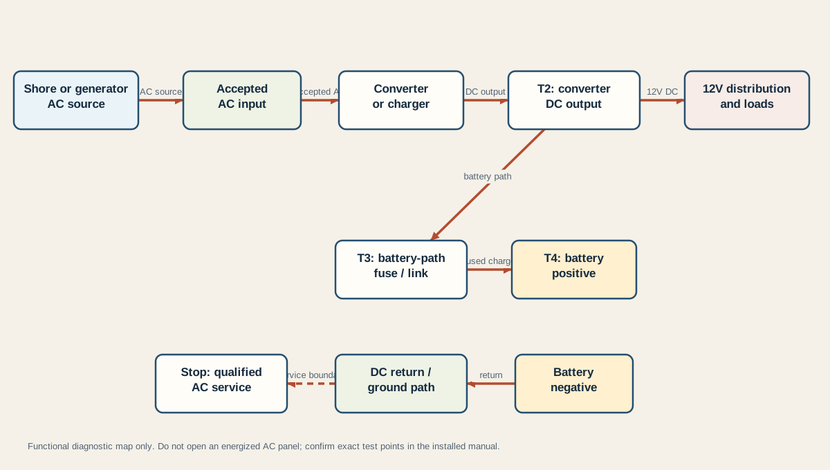
Use the last known-good node, not the most dramatic symptom, to choose the next bounded action:
| Observed result | Most defensible interpretation | Safe next action |
|---|---|---|
| Source is not accepted or an accessible breaker is tripped | The charging path has not been shown to receive its required AC input | Resolve the source issue according to the RV and pedestal/generator instructions; stop if protection trips again. |
| Source is accepted, but no model-approved converter output is present | Converter input, converter protection, or converter electronics remain possible | Follow the exact converter manual or use qualified service; do not open an AC panel from this guide. |
| Converter output is present, but the battery terminals do not follow the documented state | Battery-path fuse, disconnect, wiring, return, or battery acceptance remains possible | Inspect only visible, manual-approved protection and connections; escalate damaged or inaccessible wiring. |
| Battery terminals show a documented charging voltage, but the monitor still says “not charging” | The monitor, shunt placement, charge stage, load current, or interpretation may be wrong | Record the actual node and current direction, then compare the monitor manual and battery manual. |
| Voltage is normal at one moment and low later | The state, load, protection, temperature, or connection may have changed | Repeat a labeled comparison and stop for heat, odor, instability, or contradictory evidence. |
| A reverse-polarity or inline fuse is open | Protection operated or the path is open; the cause is not established by the open fuse alone | Replace only with the exact documented type after the cause and safe procedure are established; otherwise use qualified service. |
The diagram makes one distinction easy to miss: T2 is converter output, while T4 is battery positive after the battery-path protection. A good reading at T2 does not prove the battery receives that voltage. Conversely, a battery-terminal reading is not a direct test of the converter’s internal output. Keep those claims separate in the service note.
Minimum handoff note for a technician
If the issue needs service, hand over a short evidence packet:
- exact RV, converter, power-center, battery, and monitor models;
- shore or generator source and the time the symptom occurred;
- breaker, disconnect, fuse, and visible-connection observations;
- each reading with test node, polarity, load state, and elapsed time;
- any heat, odor, swelling, corrosion, water intrusion, or repeated trip;
- the manual sections already checked and the point where the sequence stopped.
That record is more useful than “the battery is dead” or “the converter reads low.” It tells the technician which part of the source-to-battery path is still unknown while preserving the safety boundary around mains voltage and high battery fault current.
Sources and limitations
This guide synthesizes the Progressive Dynamics troubleshooting sequence, WFCO’s public FAQ, and the WFCO Auto-Detect manual. The sources verify the need to separate AC input, converter output, battery-path protection, measurement location, and battery chemistry. They do not establish a universal voltage threshold, fuse rating, wiring diagram, or repair procedure for every RV. Product manuals, battery-manufacturer limits, applicable electrical codes, and qualified service remain authoritative for the installed system.