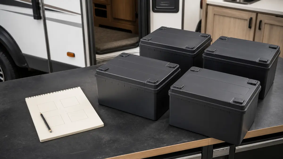
Series, parallel, and series-parallel describe how battery modules are grouped. They do not decide whether the proposed bank is compatible with the RV. Use the arithmetic to identify the nominal bank result, then pass the separate manual-evidence gate before treating that result as a candidate design.
The fast distinction is:
| Topology | Nominal voltage | Amp-hour capacity | What it changes |
|---|---|---|---|
| Series | Adds across batteries in one string | Remains the applicable single-battery Ah rating | Raises bank voltage |
| Parallel | Remains the compatible branch voltage | Adds across branches | Raises Ah capacity at that voltage |
| Series-parallel | Adds within each string | Adds across compatible strings | Reaches both a target voltage and higher Ah capacity |
Safety and limitations: A battery bank can deliver destructive fault current even when no shore power is connected. This page is a planning model, not authorization to make or break battery connections. It does not select conductors, fuses, breakers, busbars, disconnects, lugs, terminal hardware, torque, ventilation, enclosures, BMS equipment, chargers, or installation procedures. Keep the bank isolated and use the exact battery and system manuals plus qualified help whenever safe access, isolation, protection, or compatibility is uncertain.
What series and parallel change
The fixture uses four inputs: nominal voltage per battery, amp-hours per battery, batteries in each series string, and the number of parallel strings. It then applies:
battery count = batteries per series string x parallel strings
bank nominal volts = battery nominal volts x batteries per series string
bank amp-hours = battery amp-hours x parallel strings
bank nominal watt-hours = bank nominal volts x bank amp-hours
Victron’s battery-bank wiring reference distinguishes the same three operations: series increases voltage, parallel increases capacity, and series-parallel increases both. Battle Born’s 100Ah 12V manual provides product-specific series and parallel examples, but those examples establish rules for that model, not every lithium battery.
The verified cases are:
| Fixture case | Inputs | Series x parallel | Tested nominal result |
|---|---|---|---|
two-6v-series |
Two synthetic 6V, 225Ah batteries | 2 x 1 | 12V, 225Ah, 2,700Wh |
two-12v-parallel |
Two synthetic 12V, 100Ah batteries | 1 x 2 | 12V, 200Ah, 2,400Wh |
four-6v-series-parallel |
Four synthetic 6V, 225Ah batteries | 2 x 2 | 12V, 450Ah, 5,400Wh |
These are arithmetic fixtures, not recommended products or bank sizes. The values are synthetic even though the form factors are familiar in RV discussions.
Series result
For two 6V, 225Ah modules in one series string:
6V x 2 = 12V
225Ah x 1 parallel string = 225Ah
12V x 225Ah = 2,700Wh nominal
The common error is adding both volts and amp-hours. Amp-hours do not add within one series string. A second common error is treating a higher bank voltage as a free upgrade: the RV DC bus, charger, inverter, solar controller, alternator charging path, monitoring, and every connected device must be designed for that system voltage.
Parallel result
For two compatible 12V, 100Ah branches in parallel:
12V x 1 battery per string = 12V
100Ah x 2 parallel strings = 200Ah
12V x 200Ah = 2,400Wh nominal
Parallel capacity does not mean that one branch may ignore its own current path or product limits. The total bank can also support more current only when the exact battery manuals, conductors, connections, busbars, protection, and downstream equipment all permit it. This page intentionally does not calculate that current limit.
Series-parallel result
For four 6V, 225Ah modules arranged as two series strings in parallel:
6V x 2 batteries per string = 12V
225Ah x 2 parallel strings = 450Ah
12V x 450Ah = 5,400Wh nominal
The fixture also verifies energy conservation: bank volts multiplied by bank amp-hours equals the sum of each module’s nominal volts multiplied by its amp-hours. Victron’s power and energy reference supports the relationship between volts, amp-hours, and watt-hours.
Nominal watt-hours are not usable watt-hours. Temperature, age, battery limits, state of charge, load rate, cutoff behavior, reserve, and conversion losses affect useful energy. Carry the documented bank result into the RV battery runtime calculator rather than treating nominal Wh as a runtime promise.
Verify the batteries can use the proposed topology
Correct arithmetic can still describe a prohibited bank. The deterministic compatibility fixture returns manual-check-passed only when every gate below is resolved. Anything unknown returns blocked.
| Gate | Evidence needed | Block when |
|---|---|---|
| Exact model manual | Current manual for the precise battery model and revision | The manual is missing, ambiguous, superseded, or for a different model |
| Series and parallel counts | Explicit maximums or manufacturer confirmation for the proposed grouping | A count is unknown or exceeded |
| Battery-set rules | Manual-backed rules for model, capacity, age, state, firmware, chemistry, or replacement conditions | The proposed set violates or cannot demonstrate those rules |
| System voltage | Ratings for the complete DC bus, charge sources, inverter, monitoring, and loads | Any connected equipment is incompatible with the resulting bank voltage |
| Preparation | Manual-backed state-of-charge, balancing, isolation, inspection, and commissioning prerequisites | A required prerequisite has not been completed and verified |
| Protection ownership | Exact requirements for battery, string, and main protection plus conductor and disconnect coordination | A generic ratio, gauge, or diagram is being substituted for the required design |
manual-check-passed means only that the recorded proposal did not fail these six questions. It is not an installation approval, safety certificate, conductor calculation, or proof that the physical layout matches the manuals.
Do not turn “matched batteries” into a universal shortcut
Using the same model, capacity, chemistry, and condition is a conservative planning baseline when no better evidence exists, but it is not a substitute for the manual. Victron’s Lithium Battery Smart installation manual gives different mixing rules for parallel, series, and series-parallel arrangements within its own product family. It also places specific limits on series and parallel counts and gives preparation, fusing, system-cable, and BMS instructions for that product.
That nuance matters in both directions. Do not assume that two batteries may be mixed merely because both labels say 12V. Also do not publish a universal rule that every parallel bank must contain batteries from the same production batch when an exact manufacturer documents allowed replacement or expansion cases. Record what the exact manual allows and which conditions apply.
Product examples prove variability, not universality
The Victron lithium manual permits specified counts for its 12.8V and 25.6V products, requires individual preparation for series use, and distinguishes protection and midpoint rules by topology. The current Battle Born manual for its 100Ah 12V model states a series ceiling for that product and requires equal state of charge before series connection. Those two manuals are examples of why the gate exists. Their numbers must not be transferred to another model, chemistry, BMS, or installation.
The same restriction applies to fuse size, fuse location, conductor gauge, voltage drop, terminal stack, bolt length, and torque. Those values require the exact battery, conductor, protective device, equipment, fault-current, route, ambient, terminal, and installation context. Use the RV 12V fuse candidate checker and wire/voltage-drop checker for those distinct audits; this page does not pre-approve either result.
Read the generated bank diagrams
The three diagrams are generated from rv-battery-bank-topologies.json, the same fixture that the calculation and compatibility QA script reads. Lines show functional connectivity, not current direction. Boxes do not depict physical terminal positions, cable routes, protection placement, or a complete installation.
Series: one string sets the bank voltage
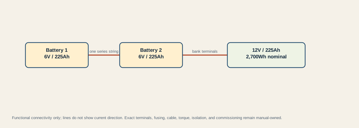
Read from left to right as one series string and then its calculated bank result. The diagram intentionally does not show which physical lug receives system wiring. That detail, including connection order, isolation, protection, and verification, belongs to the exact manual and qualified installation plan.
The result node must match all equipment on the bank. Two 12V batteries in series would produce a nominal 24V bank, not a larger 12V bank. Supplying an RV’s 12V distribution directly from that 24V result would be a system-voltage mismatch unless the system was explicitly designed with the required conversion and protection.
Parallel: comparable paths matter
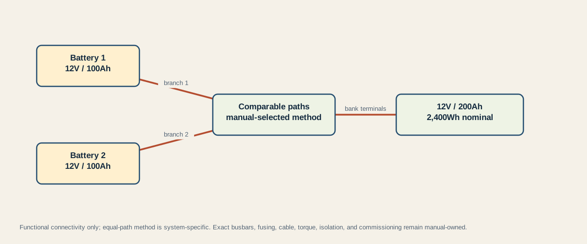
The center node says manual-selected method because there is no single layout that can be copied into every bank. Victron’s battery-bank reference documents multiple ways to obtain comparable current paths, including busbars with equal-length branch connections, suitable posts, halfway connection, and diagonal takeoff. Its discussion also explains why a one-ended daisy chain can work one battery harder: cable and connection resistance make the path lengths unequal.
A diagonal takeoff is therefore one possible method, not a universal substitute for resistance analysis or a manufacturer-approved busbar design. The exact topology, branch lengths, conductor cross-sections, fusing, connection resistance, and current limits still need verification.
Series-parallel: validate strings before combining them
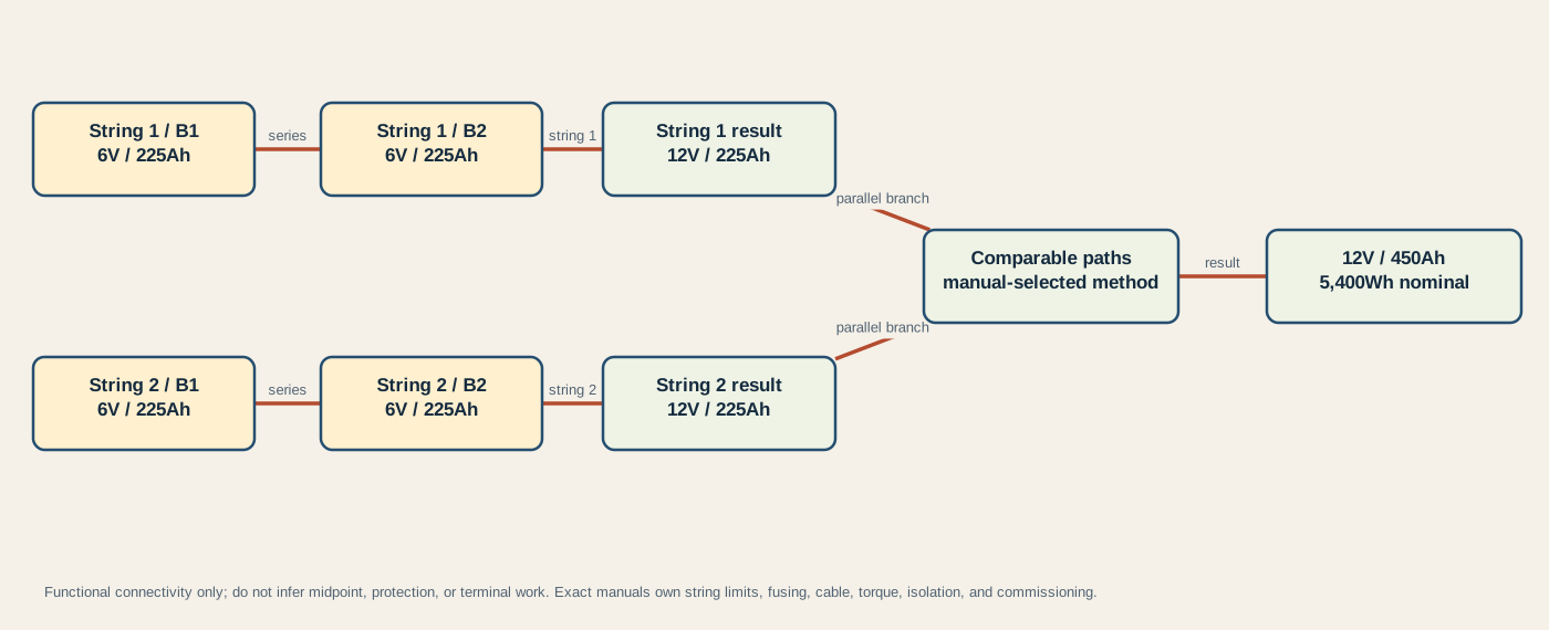
Each row first produces a 12V, 225Ah series string. The two compatible strings then combine through comparable paths to produce 12V, 450Ah. The bank result is valid only if both string calculations, the battery-set rules, and the system-voltage gate pass.
Midpoint instructions are a good test of whether guidance is truly product-specific. The broad Victron battery-bank reference describes midpoint monitoring and certain lead-acid series-parallel arrangements where midpoint connection can be useful. The Victron Lithium Battery Smart manual explicitly says not to interconnect midpoints in its series-parallel configuration. These are not interchangeable instructions. Follow the exact battery, BMS, and system manual; never connect a load to a midpoint based on a generic diagram.
Stop before topology becomes terminal work
Do not proceed from these diagrams when any of the following is true:
- The exact battery model, chemistry, manual revision, or existing bank condition is unknown.
- The proposed series/parallel count or battery-set rule is not explicitly allowed.
- The resulting voltage does not match every connected device and charge path.
- Required preparation, balancing, firmware, BMS, isolation, or commissioning steps are unresolved.
- Conductor, protection, disconnect, busbar, lug, terminal, torque, enclosure, ventilation, or fault-current requirements are incomplete.
- The bank is energized, damaged, hot, swollen, leaking, corroded, unstable, or cannot be isolated and verified safely.
At that point, preserve the proposed topology and fixture result as planning evidence, but stop physical work. Resolve the missing product documentation or use a qualified RV electrical installer who can verify the complete DC design.
Sources and limitations
The calculations use nominal ratings and identical values within each synthetic fixture. Real batteries vary with product design, age, temperature, state of charge, resistance, BMS behavior, and test conditions. The diagrams do not calculate fault current, usable capacity, charge behavior, imbalance, voltage drop, conductor ampacity, or protection. Manufacturer limits and manuals can change; recheck the exact model and revision before relying on any configuration.
Last verified: August 27, 2026. Re-verify all product and system constraints whenever batteries, firmware, charge equipment, voltage architecture, or protection changes.