
If RV lights work but the household-style outlets do not, that does not prove an outlet failed. Most house lights are 12V DC loads; ordinary receptacles are 120V AC loads. First establish whether the RV has an AC source in the current operating mode, then determine whether the symptom affects every AC load, every receptacle, one protected group, or only one device.
That order prevents three common mistakes: expecting a non-inverted outlet to work from the battery, resetting every protective device without knowing which zone it owns, and treating a reset as proof that a circuit is safe.
Safety and limitations: 120V AC can cause fatal shock, burns, or fire. This owner path is limited to documentation, externally visible condition, installed displays, and front-facing controls that the exact RV and device manuals identify as owner-operable. Do not remove a panel or receptacle cover, touch conductors, insert probes or improvised testers, bypass a GFCI or breaker, upsize protection, replace a receptacle, or repeatedly reset a device. Disconnect from a suspect source and obtain qualified RV electrical service for heat, odor, buzzing, arcing, discoloration, a loose or damaged cord or inlet, water exposure, an energized RV skin, open-ground or reverse-polarity indication, a device that trips again, or any access or state you cannot verify safely.
Confirm the receptacle should have power in this mode
Write down the mode before touching a reset button: accepted shore power, running generator, battery with inverter on, or battery without an inverter source. Also record solar and converter status, but do not mistake either for direct proof of receptacle power. A converter supplies DC from AC; an inverter supplies AC from DC. The converter-versus-inverter guide explains that boundary.
Jayco’s 2026 Class C manual describes 12V DC and 120V AC as independent systems and documents model-dependent source routing through a transfer switch, load center, and inverter/charger. That is one current manufacturer example, not a universal layout.
Airstream provides a useful example of why the exact model matters: its inverter support guidance says battery-only operation may power selected inverted outlets rather than every outlet. Other RVs can have no inverter, a different subset, a different transfer arrangement, or a separate inverter GFCI. Use the installed manuals and labels to decide what should work.
| Mode and observed scope | What the observation supports | What it does not prove |
|---|---|---|
| Battery-only, no installed inverter | Ordinary receptacles being dead can be normal | It does not prove the battery, converter, receptacles, or breakers failed |
| Battery-only, inverter on, only documented non-inverted outlets are dead | The observed pattern can match the documented design | It does not prove every marked outlet is correctly mapped or the inverter is healthy |
| Battery-only, documented inverted outlets are also dead | The inverter-fed path needs exact-product state and fault evidence | It does not justify opening the inverter or assuming it failed |
| Accepted shore or generator power, and all AC appliances plus receptacles are dead | The first unexpected zone may be upstream of individual branches | Working 12V lights do not establish AC source acceptance |
| Some known AC loads work, but every ordinary receptacle is dead | An AC source reaches at least one branch; receptacle branch ownership becomes relevant | It does not prove a breaker or GFCI is defective |
| One group of outlets is dead while another group works | The symptom can fit one branch or one upstream protected group | Physical proximity does not establish that outlets share a circuit |
| One receptacle is dead while documented downstream and comparison outlets work | The symptom is narrow, but internal device or connection work is still hazardous | It does not authorize receptacle removal or live testing |
Use a known built-in AC load only if its operating mode is documented and observation requires no access. For example, record whether a microwave display that normally operates in that mode is on. Do not use an air conditioner, heater, or other large load merely as a test. A load can also be managed, shed, switched, or protected separately, so record its identity rather than calling it “proof of good power.”
If shore equipment or source acceptance is uncertain, pause here and use the RV shore-power safety check. The receptacle diagnosis cannot start with a damaged cord, questionable pedestal, unsafe polarity/ground indication, or unaccepted source.
Collect owner-safe source and protection evidence
Preserve the failure state before changing anything. A short record makes the result useful to both you and a technician.
| Evidence field | Record without opening equipment | Why it matters |
|---|---|---|
| RV identity | Manufacturer, model, model year, floor plan, and known electrical modifications | Source routing, inverter coverage, directories, and GFCI groups can change by model or modification |
| Current source mode | Shore, generator, inverter, or no AC source; plus installed source/EMS indicators | The same outlet can be expected on in one mode and off in another |
| AC comparison loads | Named AC loads that work and do not work | An unaffected branch moves the boundary downstream of at least part of distribution |
| Receptacle scope | Every dead and working receptacle by location; note standard or GFCI face | A remote-looking outlet may belong to an upstream protected group |
| Visible protection state | Exact directory label, front-facing breaker handle, GFCI buttons, and device indicator state | Labels and indicator meanings belong to the installed product, not a generic color rule |
| Event history | What was plugged in, source transition, weather/water, overload indication, modification, or trip immediately before failure | The event can create a stop condition or identify the mode in which the symptom began |
| Physical condition | Heat, odor, sound, discoloration, looseness, cracked insulation, moisture, or damage, observed without touching suspect equipment | Any abnormal condition stops the owner sequence |
Before a permitted reset, unplug portable loads from the affected receptacle group using normal plug handling and only when there is no heat, damage, moisture, or other stop condition. Do not unplug an overheated or damaged connection under load; disconnect the upstream source by its documented safe method and obtain service.
For a front-facing breaker that the exact RV manual identifies as owner-operable, follow that manual’s complete procedure. Jayco’s named manual, for example, says to turn off the appliance on the affected circuit, allow the breaker to cool, and move a tripped handle fully off before returning it on. It also says a breaker that re-trips or frequently trips requires dealer diagnosis. Do not transfer that sequence to an unknown panel, remove a deadfront, or keep cycling a breaker.
For a GFCI, use the instructions for the exact device. Leviton’s current GFCI status guidance illustrates why: indicator colors and button position vary by series, and a device may not reset when no line power is present or when protection is unavailable. A single reset attempt that the installed instructions permit is an observation. A device that will not reset, will not remain reset, shows a persistent fault indication, or fails its prescribed test is not an invitation to replace it yourself.
Do not conclude that a standard-looking outlet is unprotected. Eaton documents that receptacles connected to a GFCI device’s load side receive downstream protection. The exact RV may instead use a GFCI breaker or multiple protected groups. Only the RV schematic, directory, labels, or qualified tracing can establish which arrangement you have.
Map the affected receptacle zone
Use the functional map below to name where evidence changes. It is not a wiring diagram, terminal map, physical location guide, or instruction to energize and probe a circuit.
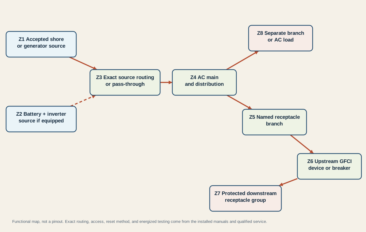
| Zone | Evidence owned by the zone | Interpretation limit |
|---|---|---|
| Z1 accepted shore or generator source | Documented connection sequence, source/EMS acceptance, generator state, and absence of source stop conditions | A lit indicator does not prove every conductor, transfer contact, or branch can carry its load |
| Z2 battery and inverter source, if equipped | Exact inverter model, on/fault state, battery state, and documented outlet coverage | “Inverter installed” does not mean every receptacle is inverted |
| Z3 exact source routing or pass-through | Installed transfer, inverter pass-through, or source-selection design from exact documentation | The generic map does not prescribe equipment order or switching logic |
| Z4 AC main and distribution | Owner-visible main state and exact directory only where the RV manual permits access | A normal-looking handle does not establish internal continuity or safe access |
| Z5 named receptacle branch | Exact branch label and which documented receptacles or devices belong to it | A room name or outlet location is not a verified circuit map |
| Z6 upstream GFCI device or breaker | Exact device identity, test/reset instructions, and front-facing state | Reset outcome alone does not prove the branch is fault-free or correctly wired |
| Z7 protected downstream receptacle group | Locations that fail and recover together under an established protected topology | One dead downstream outlet does not identify which connection or device is at fault |
| Z8 separate branch or AC load | A documented comparison branch that remains available in the same source state | It proves only that part of the upstream AC path is available, not that Z5-Z7 are safe |
Begin with the last expected zone supported by owner-visible evidence. If all AC loads are dead and the source was not accepted, the boundary is no later than Z1-Z3; do not jump to GFCI. If a separate documented AC branch at Z8 works while one receptacle group is dead, source availability and part of Z4 are supported, and attention moves toward the exact Z5-Z7 ownership.
An upstream GFCI device does not need to be beside the dead outlet. A bathroom, galley, or exterior device may protect other locations if the exact RV wiring places them downstream. Conversely, two adjacent receptacles can be on different branches. Create a simple list of locations that change together; do not infer the physical cable route.
Any physical circuit tracing, panel inspection behind a cover, continuity check, receptacle removal, conductor examination, or energized measurement belongs to qualified service. The technician should use the exact schematic and listed equipment procedures, establish isolation and absence of voltage where required, select properly rated test equipment, and record the last expected and first unexpected zone. If the topology is undocumented, the result remains UNRESOLVED until it can be established safely.
Interpret the affected zone
Use the narrowest row that matches the preserved mode and scope. These outcomes route evidence; they do not diagnose a failed component from one observation.
| Preserved result | Best current interpretation | Next action |
|---|---|---|
| Battery-only; no inverter or outlet is documented non-inverted | Normal operating-mode result | Use an accepted AC source or only outlets explicitly documented for the inverter |
| Battery-only; documented inverted outlets are dead and the inverter reports an exact-product fault | Inverter-fed path is unavailable or limited in that state | Follow only the inverter manual’s owner-level state guidance; escalate if reset/access is not explicitly authorized |
| Shore/generator source is not accepted or shows unsafe ground/polarity | Upstream source evidence fails before receptacle zones | Disconnect and use the shore-power safety process; do not bypass source protection |
| All AC loads are dead although the source is reportedly present | Z1-Z4 source-routing or distribution evidence is incomplete | Preserve indicators and obtain qualified service; do not open a transfer switch or load center |
| A separate documented AC load at Z8 works, but all receptacles are dead | At least one AC path works; a receptacle branch or protected grouping needs exact evidence | Check the exact directory and owner-accessible GFCI states once, then escalate unresolved results |
| One group is dead and an exact upstream GFCI is visibly tripped | The protected zone has opened; the cause is not yet established | Remove portable loads only when safe, perform one manual-authorized reset, and observe without bypassing |
| The GFCI resets and the group returns | The group is powered again under the observed state | Record the event; stop and seek service if it trips again, a prescribed test fails, or any abnormal condition exists |
| The GFCI will not reset | It may lack line power, detect an unresolved condition, be miswired, or be unable to provide protection | Keep the zone out of service and obtain qualified diagnosis; do not replace or bypass it from this symptom alone |
| Breaker or GFCI trips again or frequently | A protective device is responding to an unresolved overload, short, leakage, equipment, wiring, or device condition | Stop owner troubleshooting and obtain qualified service |
| Only one receptacle remains dead while its established upstream group works | The symptom is local to that device or its connection path, but the failed element is not proven | Do not remove the cover or receptacle; qualified service owns inspection and replacement |
| Receptacles work on one source but not another | The source-specific routing, transfer, pass-through, or inverter-fed subset differs | Compare exact manuals and indicators; service owns internal source-path confirmation |
| Heat, odor, buzzing, arcing, discoloration, water, damage, open ground, reverse polarity, or energized skin appears at any point | Immediate safety stop | Disconnect by the documented safe method, keep the RV unoccupied as conditions require, and obtain qualified assistance |
Do not substitute the 12V outage diagnostic for this process. That guide owns house DC loads such as lights, pump, fans, and appliance controls. This page owns 120V receptacle availability and its functional protection zones. If both systems fail, preserve both symptom sets; do not assume they share one failed part.
The useful handoff is concise: exact RV and installed equipment, source mode, accepted-source evidence, every working and dead AC comparison load, documented inverter coverage, breaker/GFCI state, one permitted reset result, event history, and the last expected/first unexpected zone. That record gives a qualified technician a safer starting point than a replaced outlet or a repeatedly reset protective device.